In this tutorial, we will learn to use GPIO pins of STM32 Nucleo board using Arduino IDE. We will see an LED blinking example using the onboard LED of an STM32 Nucleo board. In this LED blinking tutorial, we will use onboard LEDs of Nucleo to turn on and off LED with a delay of one second. By doing this experiment, you will learn how to use GPIO pins of Nucleo board as digital output pins.
Recommended Components
The following components are used in this project or are helpful for getting started with STM32 Nucleo development.
| Component | How it’s used in this project | Buy on Amazon |
|---|---|---|
| STM32 Nucleo Board (NUCLEO-F103RB) | The STM32 Nucleo-64 development board used in this guide. | Check Price |
| Micro USB / Mini-B USB Cable | Type-A to Mini-B cable to program and power the Nucleo over its onboard ST-Link. | Check Price |
| 5mm LED | External LED driven from the PC6 pin in the interfacing example. | Check Price |
| Resistor Kit (220Ω) | Current-limiting resistor for the external LED. | Check Price |
| Breadboard | Solderless board for wiring the external LED circuit. | Check Price |
| Jumper Wires | Connect the Nucleo pins to the LED and resistor. | Check Price |
As an Amazon Associate we earn from qualifying purchases. Prices and availability are accurate as of the date/time indicated and are subject to change.
Whenever any beginner starts learning any microcontroller development board, Experts always recommend beginners to start with an LED blinking example. LED blinking examples to use general-purpose input-output pins to turn on and turn off the LED. By learning how to control GPIO pins, you will be able to use GPIO pins of ESP32 board for other applications like LCD interfacing, keypad interfacing, and other embedded system projects.
Before starting this tutorial, you should have installed STM32 Arduino Core in Arduino IDE. If you have not installed it already you can follow this tutorial:
Getting Started with STM32 Nucleo in Arduino IDE
STM32 Nucleo GPIO Pins
As discussed in the previous tutorial, there are many variants of STM32 Nucleo boards are available. You can use any one of these boards. But the one which we are going to use in this tutorial is a Nucleo-F103RB board. But you can use any other Nucleo board also and follow the same instructions to use GPIO pins as digital output pins.
The Nucleo-F103RB board comes with an STM32F103RBT6 microcontroller which is ARM®32-bit Cortex®-M3 CPU. Various features of Nucleo-F103RB are mentioned below:
| Features and Peripherals | Numbers and Range |
|---|---|
| Operating voltage range | VDD from 2.0 V to 3.6 V |
| Flash Size | 128KB |
| SRAM Size | 20KB |
| GPIO Pins | 51 |
| ADC | 12-bit ADC (2) with 16 channels |
| RTC | 1 |
| Timers | 4 |
| I2C | 2 |
| USART | 3 |
| SPI | 2 |
| CAN | 1 |
According to the above table, this STM32 Nucleo board has 51 general purpose input-output pins. We can use any one of these pins as a digital input or digital output.
Each GPIO pin may have multiple functions. But you can use only one functionality at a time. The following diagrams of different connectors of Nucleo-F103RB board show various GPIO pins for UART, I2C, SPI, ADC, CAN, Timers output, and USB communication.


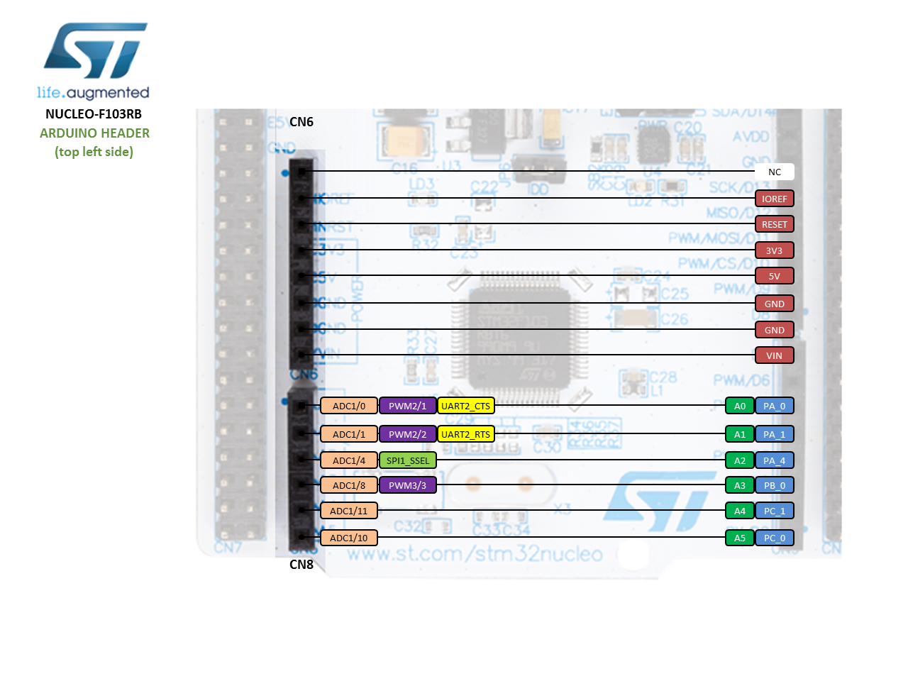
For more information on GPIO pins and to check the pinout of Nucleo-F103RB, you can refer to this link.
Use STM32 Nucleo GPIO Pins with Arduino IDE
As mentioned earlier, in this Nucleo tutorial, we will learn how to configure general-purpose input-output pins of STM32 Nucleo as digital output pins. Although these GPIO pins can also be used as digital input pins. But, we will discuss it in the next tutorial on how to use a push button with STM32 Nucleo and configure GPIO pins as digital input pins.
STM32 Nucleo-F103R has 51 GPIO pins. We can configure any one of these pins either as a digital input or digital output.
Note: On Nucleo-64 boards, PA_2 and PA_3 pins are not available per default as they are used by the STLink Virtual Comm Port.
Program STM32 Nucleo GPIO pins with Arduino IDE
To write LED blinking code for STM32 Nucleo, first, we need to understand three main functions available in Arduino IDE. These routines are used to configure GPIO pins. If you have already used Arduino IDE for Arduino, ESP32, or ESP8266 programming, you will be already familiar with these functions :
pinMode(pin_name, pin_mode)
This function is used to configure GIPO pins mode either as an input or output. The first argument to this function is a pin number or pin name to which you want to declare either as an input or output. The second argument is either INPUT or OUTPUT. For example, if we write pinMode(22, OUTPUT), it will declare pin number 22 as a digital output pin.
pinMode(PD_2, OUTPUT) // configure PD_2 pin as a digital output pin
pinMode(PA_7, OUTPUT) // configure PA_7 pin as a digital output pin
pinMode(PA_5, INPUT) // configure PA_5 pin as a digital output pin
digitalWrite(pin_number, value)
This function sets or clears digital output pins if the pin has been configured as a digital output pin with pinMode() function. A first argument is a pin number and the second value to this function is logic state either ‘HIGH’ or ‘LOW’. For example, if you write digitalWrite(PD_2, HIGH), it will make pin number PD_2 logic HIGH or 3.3 volts and if you write digitalWrite(PD_2, LOW), it will make digital output pin PD_2 LOW or you will get zero volts at the output pin.
digitalWrite(PD_2, HIGH) // sets the PD_2 pin as digital high
digitalWrite(PD_2, LOW) // sets the PD_2 pin as digital low
delay(value)
This function is used to generate delays in milliseconds. If you want to add a delay of one second between turning on and turning off an LED, you will use delay(1000).
delay(1000) // waits for one second
delay(2000) // waits for two second
setup()
In Arduino IDE, the setup function is used for declaration or initialization. A pinMode function is used for the declaration of digital pins. So it will be defined inside the setup function. It will become more clear when you see the example code at the end of this tutorial.
Loop()
In Arduino IDE, a loop function acts as the main function in c programming. In c programming whenever, you want to perform certain tasks, again and again, we use those c statements inside the loop. Similarly, we use the loop function in Arduino IDE to perform certain tasks again and again.
LED Blinking with STM32 Nucleo
As I mentioned earlier in Nucleo-F103RB, we have can use 51 GPIO pins and we can use any one of these pins as digital output pins. Now let’s select one pin and used it to turn on and turn off LED with some delay.
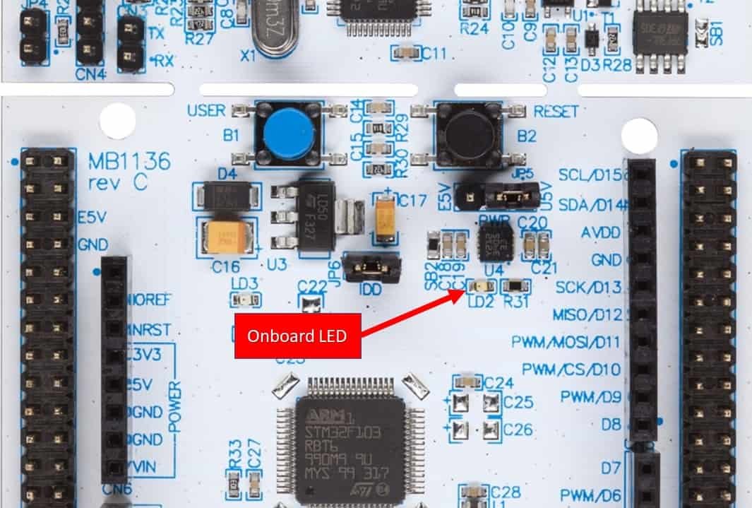
In this example, we will control an onboard LED of STM32 Nucleo-F103RB board. This STM32 Nucleo board has an onboard LED with the name of LD2 and it is connected with the PA_5 pin of F103RB as shown below:
STM32 Nucleo LED Blinking Example
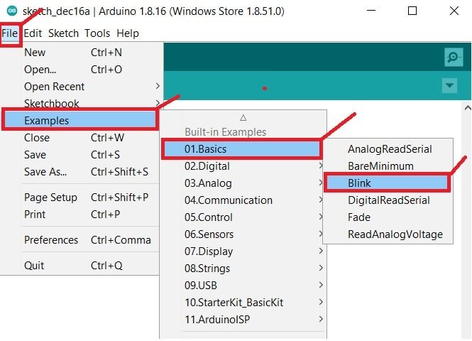
Now let’s see a sample LED blinking example available in examples of Arduino IDE. To open the LED blinking example go to File > Examples > Basics > Blink and click on it. It will open a simple LED blinking example which will blink onboard LED of Nucleo-F103RB at the rate of 1 second.
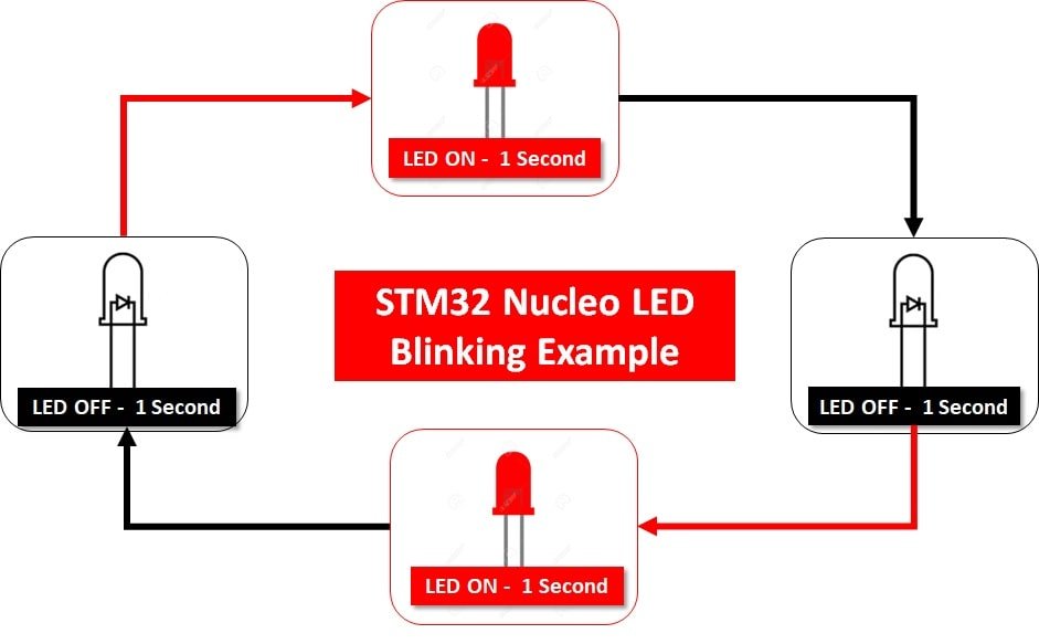
This LED blinking example works as mentioned below:
- Onboard LED Turns on for one second that means GPIO PA_5 goes to active high state
- In next step, LED turns off for one second that means GPIO PA_5 goes to active low state
- Above two steps keep repeating as shown below:
/*
  Blink

  Turns an LED on for one second, then off for one second, repeatedly.

  Most Arduinos have an on-board LED you can control. On the UNO, MEGA and ZERO
  it is attached to digital pin 13, on MKR1000 on pin 6. LED_BUILTIN is set to
  the correct LED pin independent of which board is used.
  If you want to know what pin the on-board LED is connected to on your Arduino
  model, check the Technical Specs of your board at:
  https://www.arduino.cc/en/Main/Products

  modified 8 May 2014
  by Scott Fitzgerald
  modified 2 Sep 2016
  by Arturo Guadalupi
  modified 8 Sep 2016
  by Colby Newman

  This example code is in the public domain.

  https://www.arduino.cc/en/Tutorial/BuiltInExamples/Blink
*/

// the setup function runs once when you press reset or power the board
void setup() {
  // initialize digital pin LED_BUILTIN as an output.
  pinMode(LED_BUILTIN, OUTPUT);
}

// the loop function runs over and over again forever
void loop() {
  digitalWrite(LED_BUILTIN, HIGH);   // turn the LED on (HIGH is the voltage level)
  delay(1000);                       // wait for a second
  digitalWrite(LED_BUILTIN, LOW);    // turn the LED off by making the voltage LOW
  delay(1000);                       // wait for a second
}
The above code blinks an onboard LED of Nucleo-F103RB after every one second. This is mentioned as LD2 on the Nucleo board and it is connected with the PA_5 pin of F103RB.
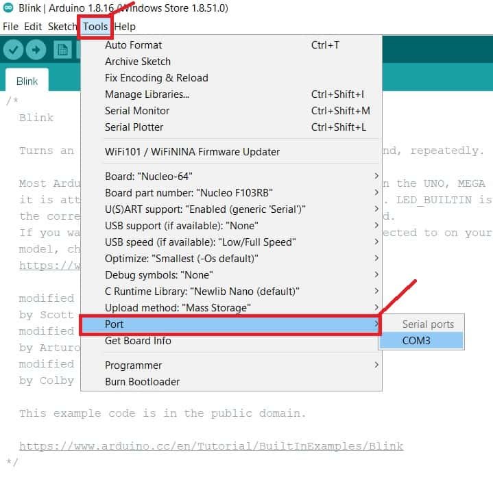
Now select the COM port to which your Nucleo board is connected. Go to Tools > Ports:
After that, compile the code and hit on upload button to upload code to the Nucleo board.

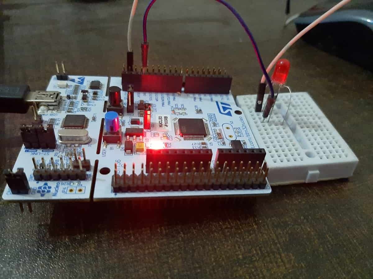
After uploading the code, you will notice that the onboard LED of the Nucleo board will start blinking as follows:

External LED Interfacing with STM32 Nucleo
Before we see how to interface an LED with an STM32 Nucleo board, we need to understand some basics of a light-emitting diode such as its current and voltage requirements. How much does it require to turn it on? What is the forward voltage rating of an LED?
LED Introduction
It consists of two terminals namely anode (+) and a cathode (-). As its name suggests, it is a light source that emits light when we apply a voltage across its terminal. We usually use it as an indication signal in embedded systems projects. For example, it is used to indicate whether power is applied to the circuit or not. Some other applications are:
- LED Flasher
- Sequencer
- Battery Level Indicators
- Back-up lights
- Traffic lights and Many others
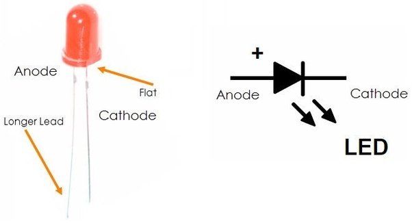
LED Terminals
This picture shows an electronic symbol and a physical diagram of light-emitting diodes. As you can depict from the diagram that it consists of two-terminal such as anode and cathode. An anode is a positive terminal and we connect the positive terminal of the power supply to this terminal. Similarly, we connect the negative terminal with the cathode.
While using an actual LED, we can find cathode and anode terminal in two ways.
- The longer lead always an anode terminal and shorter one is a cathode
- Secondly, we can identify cathode from the flat surface and another one will anode leg
LED Current and Voltage Requirement
Before interfacing LED with STM32 Nucleo, we should find its forward current and forward voltage. The intensity of lights that emits from it depends on the forward current. The greater the forward, the higher will be light intensity. But every device has a peak forward current and voltage. It cannot withstand the current and voltage greater than the peak value.
For example, if we use a RED_LED that has a brightness of 5MCD, it will operate at 10mA current.
Note: millicandela is a light intensity unit that is used to measure light brightness.
The forward voltage depends on the color and size of an LED. This table shows the forward voltage drop of different color LEDs according to color and size.
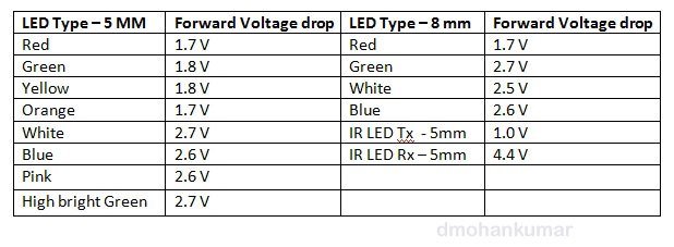
Therefore, we can conclude from the above table that the average forward voltage drop is about 2V. The typical forward current is about 10mA. But, there are small-size (1MM) LEDs also available in the market that can operate even at 1mA. But you should select the device according to your brightness requirement.
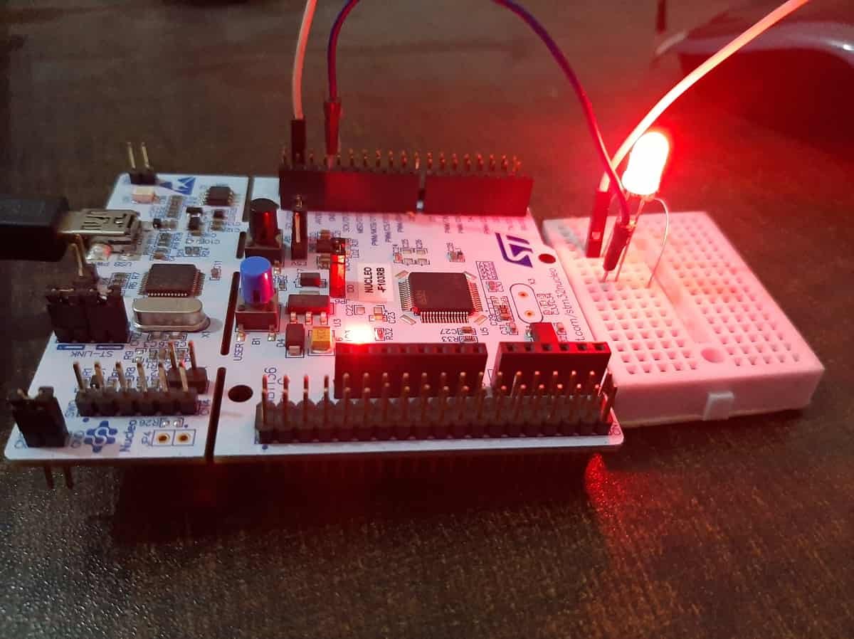
LED Connection with STM32 Nucleo Board
First, we need to decide which pin of Nucleo board we want to use as a digital output pin. In this example, we will use a PC6 pin. All GPIO pins of STM32 Nucleo provide 3.3V at its output when the pin is in an active-high state.
This diagram shows a connection diagram/LED interfacing with a Nucleo board.

Let’s assume that the forward current is 10mA. But you can always find a peak forward current value from the datasheet. We can easily calculate the current limiting resistor value (R1) by using this equation:
R1 = 3.3 - 2 / 10mA
R1 = 1.3/10mA = 0.13K = 130Ω =100Ω
That means we can use the closest standard resistor value of 120Ω. We can easily find a resistor value close to 300Ω in the market.
Why Do We Need A Current limiting Resistor?
You must be thinking why do we need to use a resistor while interfacing an LED with an STM32 Nucleo board? This is because of the current sin and source limit of GPIO pins of Nucleo boards.
Now upload this to code to STM32 Nucleo board using Arduino IDE.
//#include <Arduino.h> // uncomment this if you are using VS code

#define LED_PIN PC6
void setup() {
  // initialize digital pin LED_BUILTIN as an output.
  pinMode(LED_PIN, OUTPUT);
}

// the loop function runs over and over again forever
void loop() {
  digitalWrite(LED_PIN, HIGH);   // turn the LED on (HIGH is the voltage level)
  delay(1000);                       // wait for a second
  digitalWrite(LED_PIN, LOW);    // turn the LED off by making the voltage LOW
  delay(1000);                       // wait for a second
}
Video Demo:
In conclusion, in this tutorial, we have learned to use GPIO pins of STM32 Nucleo as digital output pins and have seen how to configure GPIO pins as digital output in Arduino IDE. In the end, we have seen an LED blinking example by using onboard LED of STM Nucleo board.
You may also like to read:
- STM32 Nucleo GPIO Pins with LED Blinking using STM32CubeIDE
- Push Button with STM32 Nucleo using STM32CubeIDE
- GPIO External Interrupts STM32 Nucleo with STM32CubeIDE
- STM32 Nucleo UART Communication Tutorial with CubeIDE and HAL Libraries
- STM32 Nucleo UART Interrupt with STM32CubeIDE and HAL Libraries
- STM32 Nucleo UART DMA with STM32CubeIDE and HAL Libraries