In this project, three phase sine wave inverter is designed using Atmega2560 microcontroller. Three phase sine wave inverter is used in many applications. It is used in many industrial as well as domestic applications. Three phase sine wave inverter is more often used in power electronics application where power requirement is greater than 10KVA. Three phase inverter is used in Three phase equipment testing. It is also used to drive three phase induction motor. It also has an application in induction motor speed control using microcontroller. I have already posted articles on single phase sine wave inverter using PIC16F877A microcontroller and You can also read my article on modified sine wave inverter. Solar inverters are also used in solar system based projects.
Working of three phase sine wave inverter
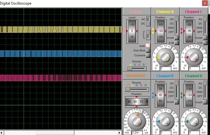
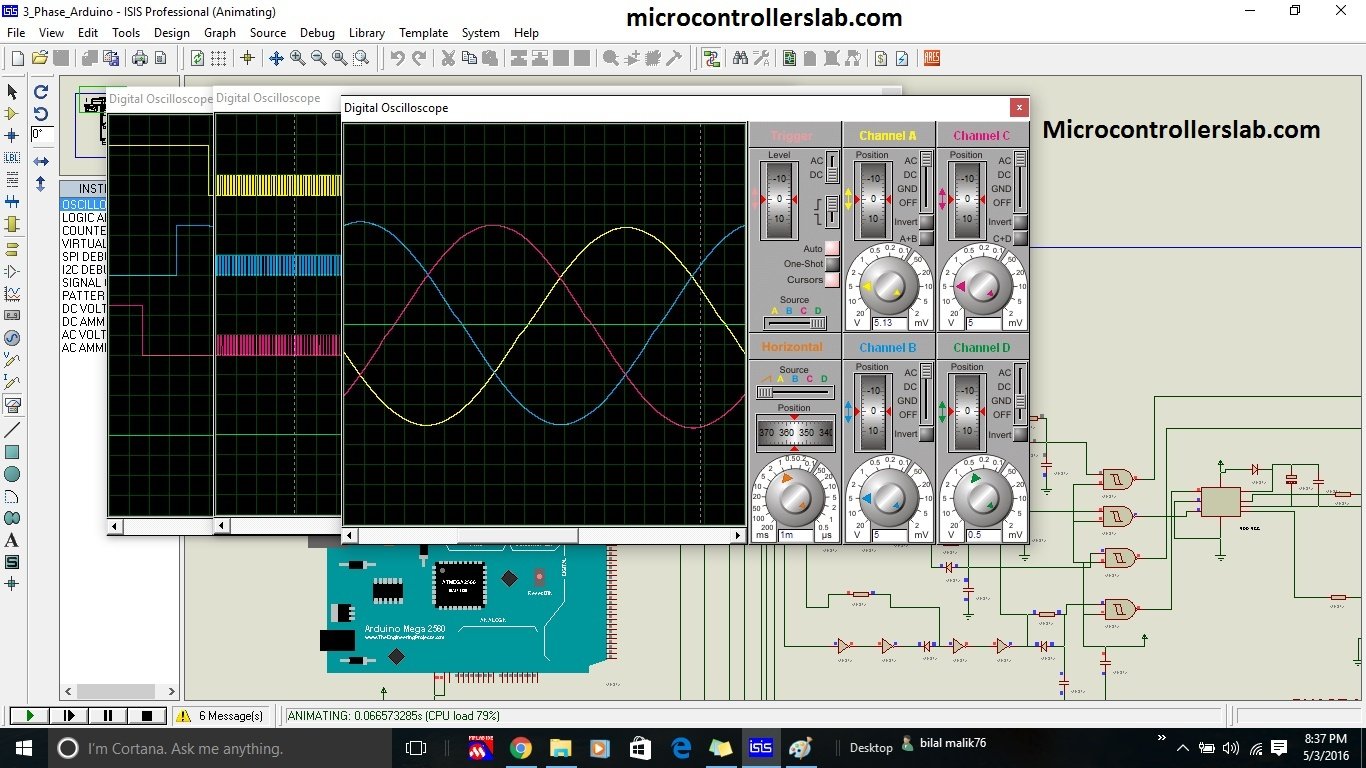
It is recommended to use it for high power applications. It can be designed using by connecting three single phase half full bridge converters. All three bridge should be operate such that all of them should be 120 degree out of phase with each other. Three phase sine wave inverter is designed using Arduino microcontroller. Arduino is used to generate SPWM singals to drive gate driver circuits as shown in figure below. These SPWM signal are 120 degree out of phase with each other. If you don’t know who to generate sinusoidal pulse width modulation signal, I recommend you read my article on SPWM generation using PIC microcontroller. After reading this article, you will get an idea about how to generate these signal to driver MOSFET drivers which are in turn used to drive MOSFET of three phase H bridge. Picture below shows the wave forms of gating signals which are 120 degree apart from each other. To completely understand working of this inverter, I recommend you to read any book on Power electronics.
Components of three phase sine wave inverter
Followings are the main components of three phase sine wave inverter:
- Arduino Atmega2560 is main components of this project. It is you can say a heart of this project. It is used to control all the signal and it is used to generate 50Hz square wave and SPWM signal which is given to MOSFET drivers which are used to drive Mosfets. Three pins five, nine and ten are used to generate three 50 HZ square waves and pin number 22, 23 and 24 are used to generate SPWM. Timers are used to generate these signals. Look up table of 50 values are stored in Arduino memory which is called again and again to generate sinusoidal signal.
- MOSFET Driver IR2112: It is used to drive MOSFET of three phase H bridge. If you don’t know how to use gate driver circuit. I recommend you to read about it first before going further in three phase sine wave inverter.
- LC filter : It is also a main component of this project. It is used to eliminate high frequency component from output voltage of three phase H bridge. you can find a proper value of capacitor in market. But you have to design inductor yourself. You can check how to design inductor if you want to design inductor.
- Rest of the components are just resistors, diodes and capacitors which are easy to use if you know how to use above mentioned components.

So to design three phase sine wave inverter, you should know how to use above mentioned electronics components. But the most important thing is that you should have an idea about how to write program for it using microcontroller.
Video results of three phase sine wave inverter
Watch the following video if you want to check results in proteus. Proteus will not simulate this circuit in real time due to high inductive and capactive components used. It will take some time for system to produce results due to excessive CPU load.
Circuit diagram of three phase sine wave inverter
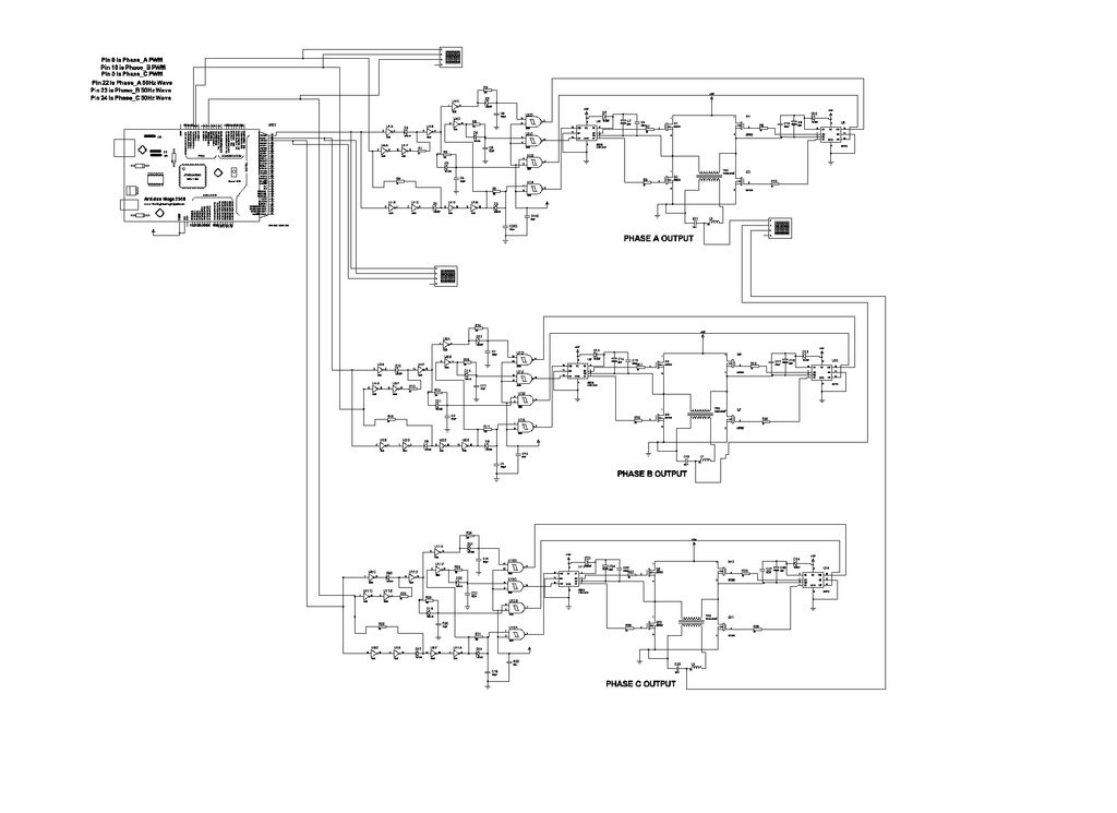
It circuit diagram is shown. It is a larger circuit diagram and it is difficult to display it properly in one picture, but still you can get an idea from this circuit diagram. I have used three single phase bridges to simulate this circuit in proteus but while implementing real time we have used only single three phase H bridge. you can use single three phase H bridge while real time implementation.
Code for three phase inverter is not free of cost. If you want to purchase code and simulation , you can buy with this button


“Code for three phase inverter is not free of cost”. As if your hardware is open, DO something about the resolution of your circuit diagram. Or is that on purpose?
No due to very high size I was not able to adjust it resolution.
Can you mail the circuit diagram just? i need it for different type of project but need to convert DC to pure AC using SPWM
sfagraphic@gmail.com
http://microcontrollerslab.com/three-phase-sine-wave-inverter/
Three phase sine wave inverter using Arduino..
Great! Can you share the squematics? Can it be adapted do ran a 380v ac motor on 3phase
My email nangnang1419@gmail.com
Many thanks..
there is 3 phase ,
can i change to 1 phase ?
yes you can.
contact me at microcontrollerslabhub@gmail.com
Hello mr.bilal Malik
Your guide about 3 phase inverter was so amazing for me but i need all of your document too make this inverter.can you send all of document of your project to my email?
Mahdifeshki@yahoo.com
I’m waiting to reply me as soon as possible.
Best regard
code is not free of cost
are you support industrial project(3phase inverter)
yes I do contact me at microcontrollerslabhub@gmail.com
how many rupee for code?
100$ or 10,000PKR
you can purchase here
http://store.microcontrollerslab.com/product/three-phase-sine-wave-inverter-using-arduino/
Hello every one
I need designe 1 phase inverter with changeable output frecuncy
Please help me
Thank lot
bro can you give me schematic and code. i will pay you.iam student.
Would it be possible for you to send me the circuit diagram and detail of cost for code? Please and thank you.
Would it be possible for you to send me the circuit diagram and detail of cost for code? Please and thank you.
Can you send me your proteus file ?
How can change frecuancy?