In this user guide we will learn to interface RCWL-0516 microwave radar sensor module with ESP8266 NodeMCU and program it in Arduino IDE for motion detection. We will discuss the components of RCWL-0516 sensor module, pinout, configuration, features, specifications, interfacing, 2D model, and applications.
We have similar guides with Arduino and ESP32:
- Interfacing RCWL-0516 Microwave Radar Sensor with Arduino
- RCWL-0516 Microwave Radar Sensor Module with ESP32
RCWL-0516 Microwave Radar Sensor Module
RCWL-0516 is a microwave radar sensor created to replace passive infrared motion sensors that utilize infrared light emitted by a moving person. RCWL-0516 uses a doppler effect technique to sense moving objects. Distance sensors are employed to measure the distance of the target by sending high frequencies. Microwaves are electromagnetic waves with VHF/UHF bands used for communication purposes. Short microwaves serve in sensing applications, especially in radars, alarm systems, and human body detection.
RCWL-0516 Components
The following figure shows the components of an RCWL-0516 module :

The module consists of an Input/Output block, an RCWL-0516 IC and RF Antenna, and an Amplifier block with some optional connections.
RCWL-0516 Pinout
Following is the pinout of the RCWL-0516 Microwave radar Sensor Detector Module :
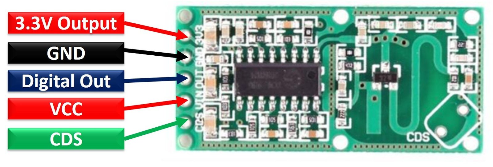
Pin Configuration
The pin configuration detail in tabular is mentioned below:
| Number | Pin Name | Function |
|---|---|---|
| 1 | 3V3 | 3.3V output pin |
| 2 | GND | Ground pin |
| 3 | OUT | Analog sensor output pin |
| 4 | VIN | Power Supply pin |
| 5 | CDS | Sensor disable pin |
Features and Specifications
- Input Operating Voltage: 4 – 28 Volts
- Operating Frequency: 3.2 GHz
- Operating Current : 2.8 – 3.0 mAmperes
- Power Transmission: 20 – 30 watts
- Output pin Voltage: 3.3 Volts
- Output pin Current: 100 Amperes
- Operating Temperature : -200C – 800C
- Range : 3 – 7 meters
- Some of the detailed features include:
- The output pin is HIGH (3.3V) when a motion is detected.
- The 3.3V output pin has a finite HIGH time of 2 -3 sec.
- Outpin pin stays at LOW state if CdS(Photoresistor) pin is less than 0.7 Volts.
- Wide operating voltage range
- Devoid of the blind angle detection
Internal Circuitry

Input/output Block: This block contains power supply pins and I/O pins connections to microcontrollers and other electronic components.
RCLW0516 IC: The IC is a system responsible for performing the doppler effect technique and is prone to fewer errors than PIR.
RF Amplifier and Antenna: An inbuilt antenna to capture the incoming waves with an amplifier to boost the module’s radio waves.
Capacitors and NPN Transistor: An NPN transistor alongside capacitors and an inductor produces oscillations at a particular high frequency. In simple words, it works as a Colpitts oscillator. The capacitors are also responsible for the decoupling and filtering of signals.
CDS: A pin to add up a light resistor to the module to make the module work only in darkness. It also functions as an enable/disable control.
C-TM, R-CDS, R-GN are used to alter the module according to the requirement. C-TM is used to elongate the trigger time of the pin by the addition of a capacitor.
To change the limit value of the photoresistor, R-CDS should be connected to a suitable resistor. Lastly, R-GN can help us to adjust the measuring distance of the sensor. Attaching it to a resistor can reduce the range of the sensor.
How does RCWL-0516 work?
The integrated antenna captures and generates the microwave signals. When the antenna receives a reflected signal, it sends it to the mixer/amplifier. It mixes the transmitted and reflected signal, and the difference between them is then passed to the IC for processing. The IC sends an output voltage signal, which showcases the distance between the body and the sensor.
Interfacing RCWL-0516 Module with ESP8266 for Motion Detection
In this section, let us show you how to connect the RCWL-0516 sensor module with ESP8266 for our motion detection project.

You will need the following components
- ESP8266 board
- RCWL-0516 microwave radar sensor module
- 5mm LED
- 220 ohm current limiting resistor
- Breadboard
- Jumper wires
The connections between the RCWL-0516 Module and ESP8266 can be seen in the table below.
| RCWL-0516 Module | ESP8266 |
|---|---|
| GND | GND |
| VIN | Vin |
| OUT | GPIO13 (D7) |
We are using Vin pin of ESP8266 to connect with the Vin pin of the sensor module. The OUT pin of the sensor module is connected with GPIO13 (D7) of ESP8266. Moreover, we will connect an LED with the ESP8266 as well. Whenever, motion will be detected, the LED will turn on for a few seconds. The LED is connected with GPIO14 (D5) of ESP8266 through a 220 ohm current limiting resistor. All the components have a common ground.
Follow the schematic diagram below for ESP8266, sensor module and LED and connect them accordingly.

Setting up Arduino IDE
We will use Arduino IDE to program our ESP8266 development board. Thus, you should have the latest version of Arduino IDE. Additionally, you also need to install the ESP8266 plugin. If your IDE does not have the plugin installed you can visit the link below:
Arduino Code: ESP8266 Motion Detection with RCWL-0516 Sensor Module
Open Arduino IDE and copy the following sketch in a new file and save it.
int detectPin = 13;
bool detect = false;
int led = 14;

void setup() {
 Serial.begin(115200);
 Serial.println("Starting...\n");
 pinMode (detectPin, INPUT);
 pinMode (led, OUTPUT);
 digitalWrite(led, LOW);
}

void loop() {

 detect = digitalRead(detectPin);
 if(detect == true) {
 digitalWrite(led, HIGH);
 Serial.println("Movement detected");
 }
 else {
 digitalWrite(led, LOW);
 }
 delay(1000);
}
Working of Code
When this motion detector sensor senses a motion, it triggers its output pin to active high state for 2-3 seconds and after that it goes to active low state again. As soon as a motion is sensed, the serial monitor will display motion detected message and the LED turns ON.
The digitalRead() function is used to measure the active high state of the distance sensor.
Demonstration
Choose the correct board and COM port before uploading your code to the board. Therefore go to Tools > Board and select NodeMCU 1.0.
Select the NodeMCU module as follows:

Then, go to Tools > Port and select the appropriate port through which your board is connected.
Click on the upload button to upload the code to ESP8266 development board.
After you have uploaded your code to the ESP8266 development board, press its RST button.

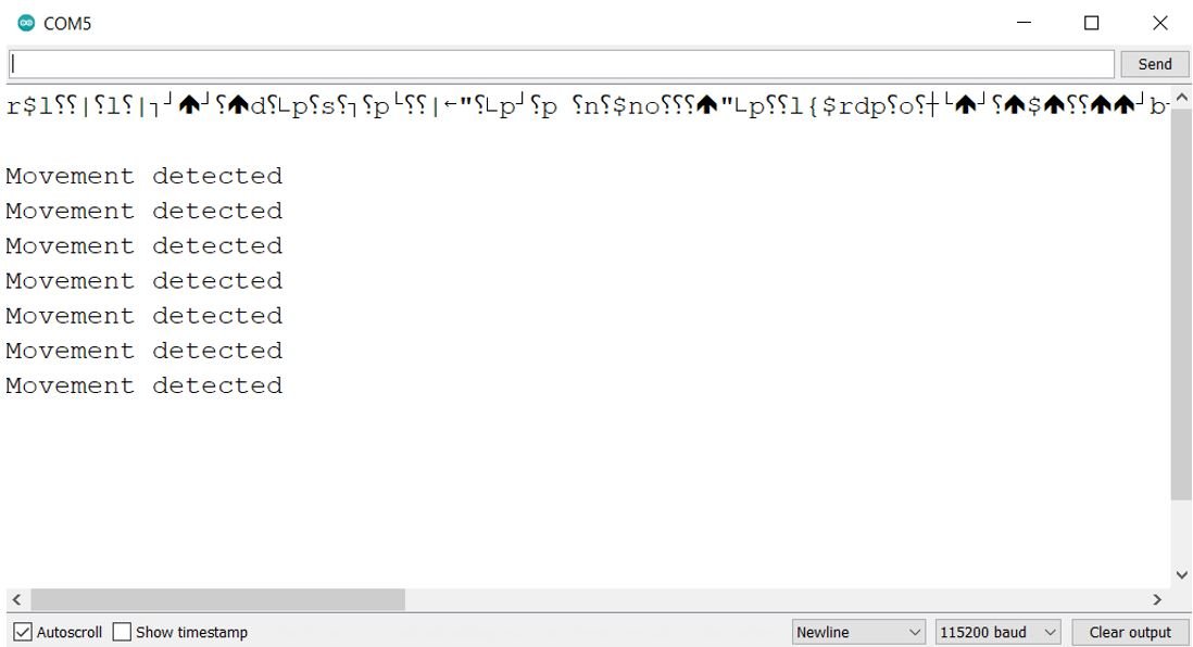
Open up the serial monitor and set the baud rate to 115200. Now whenever there is a motion in front of the RCWL-0516 microwave sensor, it will detect the sensor and display the “Movement detected” message on the Arduino serial monitor. Moreover, the LED which is connected with GPIO14 pin of ESP32 also turns on.

RCWL-0516 Alternative Options
- SEN0192
- HC-SR04
Applications
- Home Automation systems
- Radars
- Intrusion alarm systems
2D Diagram
The following figure shows the 2d model of the RCWL-0516 Microwave Distance Sensor Module. It shows us the physical dimensions of the components needed when a PCB card is designed.

- HC-SR04 Ultrasonic Sensor Interfacing with TM4C123
- VL53L0X LIDAR Distance Sensor Interfacing with Arduino
- HC-SR04 Ultrasonic Sensor Interfacing with Pic Microcontroller – Distance Measurement
- Pic Based Ultrasonic Radar System for distance measurement
- Display of Underground Cable Fault Distance Over Internet
- HC-SR04 Ultrasonic Sensor Interfacing with Arduino – Distance Measurement Example
- APDS9960 Proximity, Gesture and Ambient Light Sensor Interfacing with Arduino
- HC-SR505 PIR motion sensor Module