In this tutorial, we will discuss the workings of a single phase cycloconverter. Then we will see how to design the circuit. At first, we will provide a basic introduction to cycloconverters. Then we will design its circuit and compare the simulation results with the theoretical discussion.
Introduction to Cycloconverter
A cycloconveter constructs a lower-frequency alternating voltage wave from a high-frequency alternating voltage wave. It does this through some switching arrangements of SCRs (silicon control rectifiers) or thyristors. Cycloconverter applications include VVVF (variable voltage variable frequency) AC drives, which run the AC motors of the cement and steel industries. Beside this, these types of cycloconverters also find applications in the aircraft and naval ship industries, where motors are driven at variable or constant speed. Different types of cycloconverter drives, such as single-phase to single-phase, three-phase to three-phase, and three-phase to single-phase AC drives, are available in the market.
Simulink Design of Single Phase to Single Phase Cycloconverter
Here we will design a single phase to single phase cycloconverter with the help of the MATLAB Simulink library. Also, we will see how to build a new model in MATLAB Simulink. First, we will open the Simulink library browser, and for the Simulink library browser, we will just open MATLAB and then click on Simulink library. A new page will open, as shown in the figure below.

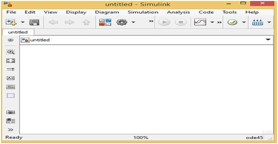
The Simulink library browser has different options on its menu bar, but for new models. We will click on the “New Model” option, and then a new page will open, as we can see in the figure below.
Placing Component Blocks
With this new Simulink model, we can make any circuit we want, but for a new circuit, we will have to choose the components. Because we are going to make a single phase to single phase cycloconverter, we require a power electronics component. For searching power electronics components, just write the word power electronics on the search menu bar. A new page will open with different power electronics component blocks. This is shown in the figure below.

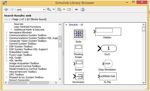
Hence, for searching the component blocks such as oscilloscope, display, etc., we can simply write the word sink on the search menu bar of the Simulink library browser, and a new page will open. Refer to the figure below.
Simulink Model
Similarly, we can easily search all the other blocks, such as voltmeter, ammeter, pulse generator, resistor, AC supply voltages, etc. After searching all the blocks, drag all these blocks onto a new model page, or we can also add all these blocks to a new model page using the right-click and “Add Block to a New Model” option. Now we will make a new model of a single phase to single phase cycloconverter with the help of all these blocks. First, we will drag all blocks onto this new model page, then joint them according to the single phase to single phase cycloconverter. Refer to the figure below.

Simulation
In this single phase to single phase cycloconverter, we set the 200 V AC voltages at 50 Hz in the AC voltage source block, along with one pulse generator for every leg of this cycloconverter. Each pulse generator gives the trigger pulse to every leg in such a way that one thyristor remains ON simultaneously. Here, we use a 20% duty cycle and a 60 Hz frequency in every pulse generator. The switching pulses of these four-pulse generators are shown in the figure below.

We can see that none of the thyristors turn on simultaneously; rather, they turn on one after the other. This is the main technique that we use in this single phase to single phase cycloconverter. The input and output AC voltages of this single phase to single phase cycloconverter are shown in the figure below.

This is all about the simulation of a single phase to single phase cycloconverter using MATLAB Simulink.
Video Demonstration
Conclusion
In conclusion, this tutorial provides an in-depth overview of designing and simulating a single phase cycloconverter. It covers step-by-step procedures along with explanations to help us better understand the concept with examples. You can utilize this concept to design and simulate more complex single phase cycloconverters. Hopefully, this tutorial was helpful in expanding your knowledge in regards to designing and simulating using Simulink.
You may also like to read:
- ESP32 ESP-NOW Getting Started Tutorial with Arduino IDE
- Raspberry Pi Pico W MicroPython Publish Sensor Readings to Google Sheets
- GPIO External Interrupts STM32 Nucleo with STM32CubeIDE
- LCD Interfacing with TM4C123 Tiva LaunchPad – Keil uvision
- ESP32 NTP Server-Client: Getting Current Date and Time Arduino IDE
- Getting started with Keil uVision: Write your first Program for Tiva LaunchPad
This concludes today’s article. If you face any issues or difficulties, let us know in the comment section below.
Great Post Brother!
I got a lot of information from it.
Thanks and keep it up!
Did you get the results of the input and output like he made?