In this tutorial, we will explain the workings of LabView software with the help of an example project. The project discussed here is a simple mini-project, and its implementation is explained with an explanation of every step. We will try to blink an LED in the block diagram of LabVIEW with the help of a switch and then blink it multiple times up to a specific number of iterations or until a specific condition is fulfilled. At the end of the tutorial, we have provided an exercise for you to do on your own, and in the next tutorials, we will assume that you have done those exercises, and we will not explain the concept regarding them.
Switch Control with LED in LabVIEW
We can control an LED with the help of a switch. For emulating purposes, we will use LabVIEW’s VI to operate an LED controlled by a switch. In this setup, first, we will design the front panel by placing elements, i.e., an LED and a switch. After this, we will connect the circuit with the help of a block diagram that sends commands either by clicking or toggling the switch, and the LabVIEW program will respond to the switch’s state change. If the switch is turned on, the LabVIEW code triggers an action that simulates the LED lighting up, altering its visual appearance. Similarly, switching off the virtual switch results in the LED being turned off in LabVIEW’s VI.
In the next section, we will see how to build this and simulate it in LabVIEW with the help of an example.
LabVIEW LED Control Example with Switch
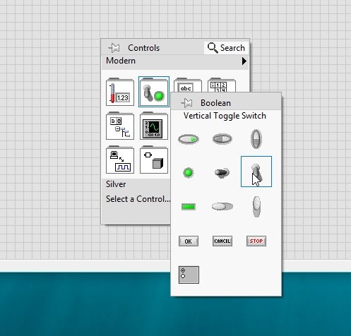
Let’s work with the LEDs, create a VI in LabVIEW as we have done in Tutorial 1, and save it for future use by selecting File >> Save as or by pressing <Ctrl+S>. From the control palette, i.e., a dropdown by right-clicking on the front panel, select Boolean, and then select the vertical toggle switch as shown in the figure below.
Now, from the Control Palette on the Front Panel, select Boolean and then select Round LED, as shown in the figure below.

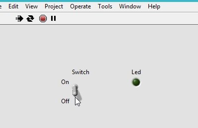
Label each of the blocks on the front panel for convenience, as shown in the figure below.

Block Diagram
The switch will act as a control, and the LED will act as an indicator in this case. Connect the output terminal of the switch (control) to the input side of the LED (indicator), as we have been doing from the start. The resulting block diagram will look like the one shown in the figure below.

Now, when we run the VI continuously, we can control the round LED with the toggle switch. Label the positions of the switches as we have discussed in previous tutorials, and also align the blocks as we have been doing.
Implement all the tricks we have learned so far in the projects we will be doing in the upcoming tutorials. When the switch is turned downward, the LED will be off, as shown in the figure below.
VI is running continuously, and during the run time, change the present state of the switch, and the LED will turn on as shown in the figure below.

Now let’s blink the LED continuously using a ‘for’ loop as we have used in previous tutorials. When the iterative index is even, the LED will not glow, and when the iterative index is odd, the LED will turn on.
Placing For Loop
From the Function Palette, select Structures and then select For Loop, as shown in the figure below.

Remove the toggle switch and place the LED inside the loop, as shown in the figure below.

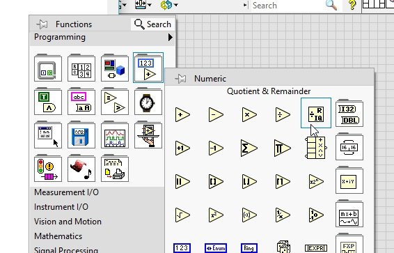
Create a constant at N, giving it a value for the loop index. Now we have to set up a situation for the LED to turn on and off. From the Function Palette, select Numeric, and then select Quotient & Remainder, as shown in the figure below.
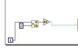
Connect one input of this block to the iterative index, and at the other, create a constant of value 2, and at the output, place a Not Equal To 0? block. From the Function Palette, select Comparison, and then select Not Equal To 0?, as shown in the figure below.

At the output of this block, connect the input of the LED. The resulting block diagram for the even-odd condition is shown in the figure below.
Wait Block
Also, place a wait block that will decide the time of iteration. From the function palette, select timing, and then select wait (ms), as shown in the figure below.

On the input side of this block, create a constant and set its value to 500, as shown in the figure below.

Now run the VI continuously, and the LED at the front panel will start blinking after each 500 ms of time. The loop will complete a single iteration after 500 ms, and the iterative index will increment by 1. According to our specified condition, when the iterative index is odd, the LED will glow. And the iterative index will switch from an even to an odd number after every 500 ms, and the LED will glow for 0.5 sec and remain off for the next 0.5 sec.
Exercise
- Using the knowledge you have gained so far, design a VI in which the LED will keep on blinking until a stop button is pressed.
(Hint: Try using a while loop.)
Conclusion
In conclusion, this tutorial has provided a comprehensive overview of controlling LEDs using switches in LabVIEW. It also covers step-by-step procedures for designing a block diagram for this purpose. This helps us understand the principle of controlling Booleans with the help of switches. Here we have also provided an example for automating the LED’s turning on and off for a certain time. You can utilize this concept in various applications, which include specific timers for controlling an event. Lastly, an exercise is provided to reinforce the concept of switch control in LabVIEW. We hope that this tutorial has been helpful in expanding your knowledge of LabVIEW programming.
You may also like to read:
- Control ESP32 Outputs using Google Assistant and Adafruit IO
- ESP32 MicroPython Publish Sensor Readings to Google Sheets via IFTTT
- ESP32 Save Data to Flash Permanently using Preferences Library
- DHT22 Sensor with STM32 Blue Pill using STM32CubeIDE
- ESP32 with MPU6050 Accelerometer, Gyroscope, and Temperature Sensor ( Arduino IDE)
This concludes today’s article. If you face any issues or difficulties, let us know in the comment section below.