Recommended Components
The following parts are used in this article, along with a generic electronics kit that is handy for building and testing the circuit.
| Component | How it’s used | Buy on Amazon |
|---|---|---|
| AD623 instrumentation amplifier | The AD623 low-cost instrumentation amplifier this article covers. | Check Price |
| Electronic component assortment kit (1390 pcs) | A handy assortment of resistors, capacitors, LEDs, diodes and transistors for building circuits. | Check Price |
| Digital multimeter (AstroAI) | Measures voltage, current, resistance and checks continuity while you build and debug. | Check Price |
| Breadboard | Solderless base for prototyping the circuit. | Check Price |
| Jumper Wires | Make the connections on the breadboard. | Check Price |
As an Amazon Associate we earn from qualifying purchases. Prices and availability are accurate as of the date/time indicated and are subject to change.
AD623 Pin Configuration Diagram
The pinout diagram shows the pin assignment of each pin.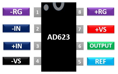
Pin Description
The description of all eight pins of the AD623 IC is given below:Pin#01, 08: -, +
These two are the inverting and non-inverting pins used to set the gain of the amplifier by connecting an external resistor between these two pins.Pin#02, 03: -IN, +IN
These two are the input pins of the amplifier.Pin#04, 07: -Vs, +Vs
These two are the positive and negative power supply connections. It provides both singly-supply and dual supply operations.Pin#05: REF
The reference input is used to establish the common-mode voltage of the output.Pin#06: OUTPUT
This pin displays the output of the instrumentation amplifier.Equivalent Op-Amps
- AD620, INA333, AD600, AD602, AD621, AD624, AD626, AD630, AD636
AD623 Features
- Rail to rail instrumentation amplifier which can operate using Single and Dual supply voltage
- Range of single supply voltage is −Vs = 0 V, +Vs = 3.0 V to 12 V.
- The range of dual supply voltage is ± 2.5 V to ± 6 V.
- It has low input and output voltage offsets.
- The maximum supply current for this chip is 550 µA.
- An adjustable gain range of 1 to 1000 which can be set using only one resistor.
- It has higher performance.
- For a single supply, the input voltage range extends 150 mV below ground.
- The bandwidth of this IC is 800KHz.
Where to use it?
AD623 possesses low noise, low DC offset and adjustable gain that can be set by a single resistor. You can use this IC in the circuits where high accuracy and both short and long-term stability are required. Its high input impedances make it suitable for use in measuring equipment. Their high common-mode rejection ratio (CMRR) makes it suitable for a wide range of multiple circuits. It is intended for low voltage applications requiring above mentioned features for their operation.How to use AD623 Op-Amp?
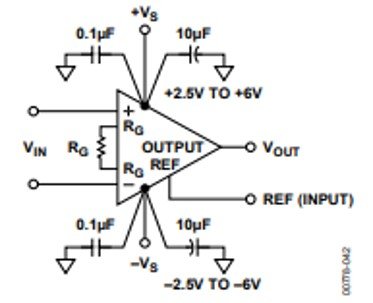
The setup of this IC is simple. An input signal provides at pins 2 and 3. The 10µF and 0.1F capacitors connect at power pins for decoupling power supplies. The RG resistor is programmed to adjust the gain When it is left unconnected, the resistance between the two terminals will be equal to infinity and gain is 1. We can calculate the gain using the following equation:RG= 100 kΩ/ (G − 1)
Connections for Dual Supply Example Circuit
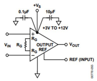
Connections for Single supply Example Circuit
 The output voltage measures with respect to a reference pin. It is connected to ground for ground referenced outputs. In general operational amplifiers, the voltage of output is not equal to the supply voltage due to output stage transistors. These transistors prevent the op-amp IC’s from reaching the maximum or minimum voltage. The AD623 IC prevents this problem by providing a rail to rail output swing. The output voltage can reach a maximum positive voltage or maximum negative voltage.
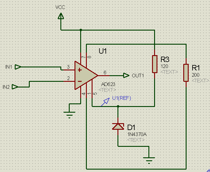
Differential amplification with the AD623
Applications
Some major applications of instrumentation amplifier AD623 include:- Cable systems for amplification of the high-frequency signal.
- Medical instruments, radars, etc.
- Audio applications for enhancing the signal to noise ratio
- Thermocouple amplifiers, industrial process controls, and difference amplifiers are the applications of this chip.
- It is used in data acquisition devices also.
2D DiagramX
The two-dimensional packages of this chip include PDIP, SOIC, and VSSOP. The 2D diagram of the PDIP package is given.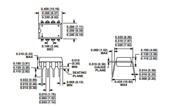
very informative post and learn alot thanks for sharing