ATtiny88 is one of the cheapest and smallest 8-bit microcontrollers with CMOS technology which also comes in 8-kb programmable flash memory. This IC comes in multiple packages with 28-pins, which can be used for multiple purposes which almost cover every application, and it also is designed with AVR RISC Architecture. The performance of the microcontroller can be optimized by the designer, the internal architecture gives the ability to the designer to optimize between speed and power consumption. ATtiny88 microcontroller can work with multiple application and its power save modes gives the ability to work on battery power with other applications.
Recommended Components
The following parts are used in this article, along with a generic electronics kit that is handy for building and testing the circuit.
| Component | How it’s used | Buy on Amazon |
|---|---|---|
| ATtiny88 microcontroller | The ATtiny88 8-bit AVR microcontroller this article covers. | Check Price |
| Electronic component assortment kit (1390 pcs) | A handy assortment of resistors, capacitors, LEDs, diodes and transistors for building circuits. | Check Price |
| Digital multimeter (AstroAI) | Measures voltage, current, resistance and checks continuity while you build and debug. | Check Price |
| Breadboard | Solderless base for prototyping the circuit. | Check Price |
| Jumper Wires | Make the connections on the breadboard. | Check Price |
As an Amazon Associate we earn from qualifying purchases. Prices and availability are accurate as of the date/time indicated and are subject to change.
ATtiny88 Pinout Details
The pin configuration details of for DIP package is given below: The pinout diagram for the SMD package is given here:
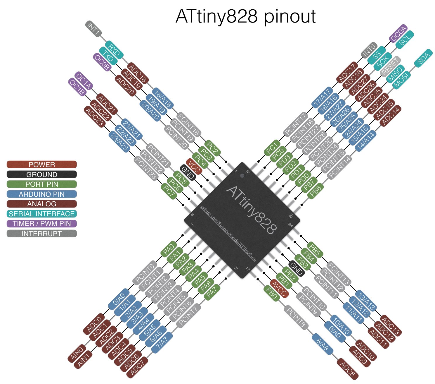
Pin Configuration Details of all Pins
POWER SUPPLY PINS
The number of power pins in ATtiny88 is three, from which one is used for power input and the remaining two can be used as a ground pin. The ground pins are internally connected and can be used for common ground by any device or the power supply that is being used with the microcontroller.
- VCC – Pin7
- GND – Pin8
- GND – Pin 22
OSCILLATOR/CLOCK PINS
The microcontroller can use the internal oscillator which is 8MHz and can be variate at a different level through programming. In the case of using the external clock, the oscillator pins can be used which can be used to extend the oscillator up to 12MHz. The oscillator/ Clock pins are:
- CLKI – GPIO9
- CLKO – GPIO14
DIGITAL INPUT/OUTPUT PINS
ATtiny88 has three GPIO ports which are 8-bit. Port A only exists in some packages Most of the pins can be used for output/input functions. All these ports also come with an internal pull-up resistor, they also have sink and source ability. ALL input and output pins on ATtiny88 are:
- PB0 – GPIO14
- PB1 – GPIO15
- PB2 – GPIO16
- PB3 – GPIO17
- PB4 – GPIO18
- PB5 – GPIO19
- PB6 – GPIO9
- PB7 – GPIO10
- PC0 – GPIO23
- PC1 – GPIO24
- PC2 – GPIO25
- PC3 – GPIO26
- PC4 – GPIO27
- PC5 – GPIO28
- PC7 – GPIO21
- PD0 – GPIO2
- PD1 – GPIO3
- PD2 – GPIO4
- PD3 – GPIO5
- PD4 – GPIO6
- PD5 – GPIO11
- PD6 – GPIO12
- PD7 – GPIO13
INTERRUPT PINS
An interrupt is function is used to get the attention CPU. When there is only one interrupt then it is easy to understand it but ATtiny88 comes with two interrupts in the same microcontroller. In two interrupt systems whenever both interrupts will be trigger at the same time then only one which executed later will be work. In this microcontroller the interrupt pins are:
- INT0 – GPIO4
- INT1 – GPIO5
SPI Communication PINS
ATtiny88 has a fully operated SPI communication system that can be used to communicate multiple sensors and multiple measuring modules to works smartly. To use the SPI protocol four pins are required. All those pins are listed below:
- MOSI – GPIO17
- MISO – GPIO18
- SCK – GPIO19
- SS’ – GPIO16
MOSI and MISO are for data sending and receiving, SCK is used to send the clock pulse to the device to transmit and receive the data according to time and the final pin SS is used to select the device. Here officially microcontroller has only one slave select pin but almost ever output pin can be used as SS’ pin through programming in case of requirement.
I2C COMMUNICATION PINS
As we discussed above an SPI communication system which is three know as a three-wire communication system but some sensors and modules use the I2C protocol due to their designed architecture. To use the I2C protocol with ATtiny88 following pins will be used:
- SCL – GPIO28
- SDA – GPIO27
SDA is used to send and receive data which makes it one-way communication at the same time and SCL is used to send the clock pulse.
TIMERS ATtiny88 Microcontroller
The IC also comes with two internal timers. Both get the input pulse from the external pins and can be operated internally. One timer (Timer0) is 8-bit and the other timer Timer1 is the 16-bit timer. Timer pins are:
- T0 – GPIO6
- T1 – GPIO11
TIMER/COUNTER OUTPUT COMPARE Module ATtiny88
ATtiny88 comes with a timer/counter output compare. The timer can be used to count pulses and even two output signals can be received at a specific time. These two output pins can be used to generate the PWM Signal. In ATtiny88 this timer can be used to count according to the input pulse. Input and output pins are given below:
- ICP1 (Input) – GPIO14
- OC1A (Output1) – GPIO15
- OC1B (Output2) – GPIO16
ANALOG COMPARATOR PINS
This microcontroller gives the ability to receive an analog input signal and then compare it. The output of the comparator can be used for further function. Event on the output of the analog comparator should be described by the program within the controller, otherwise, it will all be wasted. Analog comparator input pins are:
- AIN0 – GPIO12
- AIN1 – GPIO13
ANALOG TO DIGITAL CONVERTER
ATtiny88 has 10-bit analog to digital converter which can be used by 6-analog input channels. Every channel converts the analog input signal to digital then store it within a 10-bit register. Analog pins in ATtiny88 are:
- ADC0 – GPIO23
- ADC1 – GPIO24
- ADC2 – GPIO25
- ADC3 – GPIO26
- ADC4 – GPIO27
- ADC5 – GPIO28
AVCC PINS
The analog to digital converter of the ATtiny88 requires external voltage to operate. This voltage can be provided through an external pin AVCC. In every condition even ADC of the microcontroller is not used, the voltage should be provided on the pin.
- AVCC – GPIO20
RESET PIN
There is one reset pin on the microcontroller which can be used externally by any device. The microcontroller can also reset from internally. The internal and external reset will have the same function and effect on the controller. External reset will be active low.
- RESET’ – GPIO1
Block Diagram ATtiny88 Microcontroller
The block diagram of the microcontroller ATtiny88 is given below:
ATtiny88 Microcontroller Features
There are multiple types of peripheral in the controller which has multiple uses:
SELF PROGRAMMING: The microcontroller comes with a self-programming feature which gives the ability to the microcontroller to program itself. In self-programming, the program is stored in the boot sequence and whenever the device is started it enables the device to program the data to the program memory according to any external or internal device as per self-program instructed.
TIMER/COUNTER OUTPUT COMPARE: This timer/counter output compare is an internal counting method used to count clock pulses. These clock pulses can be broken down with Prescaler to minimize the minimum counting limit. It is also attached to the external output pins which generate the output whenever the internal clock cycle has completed its limit. The ATtiny88 has two timers one is 8-bit and the second one is 16-bit time.
DEBUG PIN: Almost all microcontrollers can be programmed by serial or parallel methods, but some devices come with some other programming method. This microcontroller can be programmed by the SPI protocol. To program any microcontroller any device which has SPI pins will require a debug pin. In most of the microcontroller debug pins comes within the reset pin. ATtiny88 also has debugger pins that can be used by MOSI, MISO, and SCK pin to program the microcontroller.
POWER VARIATION: This feature doesn’t come in most of the microcontroller. This power variation gives the ability to the programmer to variate the performance and power consumption of the controller according to the requirement. Both power and performance have direct relation, in case of increasing performance the power consumption will be increased automatically.
WATCHDOG TIMER: It allows the device to reset itself in case of an error or getting stuck at some instruction to keep performing the operating and to keep the device active.
ATtiny88 Microcontroller Programming
To program Atmel microcontrollers, we always need a compiler. These are the popular compilers used for programming in c language or assembly language.- Atmel Studio ( Getting started guide on Avr studio)
- Mikro C for AVR
- AVR – GCC
- AVR – toolchain for Windows and Linux
2D Model
The dimension diagram for a 28 pin DIP package is shown here.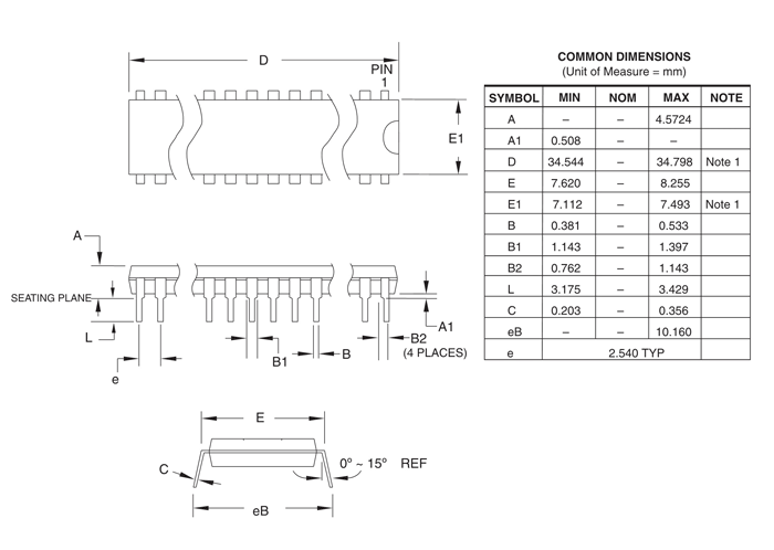
Applications Attiny88
- ATtiny88 is used in measuring and manipulation of analog signal output data.
- In industries, most of the small digital systems use ATtiny88 due to its power variation method.
- Power Regulation and SMPS uses the ATtiny88 to perform control operations.