Video Transcript of Boost Converter Proteus Simulation
Boost Converter Introduction
In this tutorial, you will learn, how to design proteus simulation of the Boost converter.
As you know that, Boost converter is a power electronics converter, it converts low voltage into high voltage. The Boost or step-up converter is a configuration that converts a voltage output, which is above the input voltage. In other words, the Boost converter boosts the input voltage to a high voltage.
Proteus Circuit Diagram
This is a circuit diagram of a Boost converter. It consists of an inductor, diode, capacitor, and a switching device. You can refer to any power electronics textbook for its working.
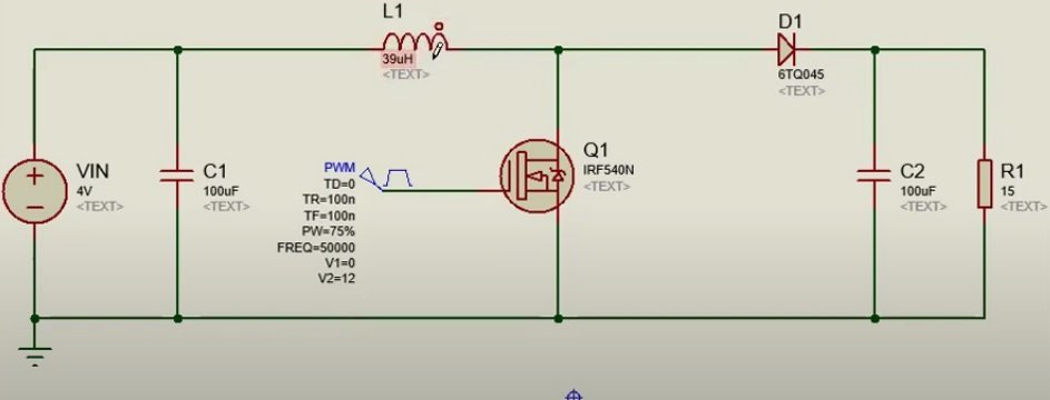
With the shown component values, the converter works by ensuring a continuous current through the inductor, for this reason, it’s known as a continuous mode. By reducing the inductor value, the converter will move in the discontinuous mode.
The voltage output can be calculated by this formula:
Vout = Vin * T/(T-T1) where:
Where T is the PWM period And, T 1 is an OFF time of PWM.
For this example, we will convert 4 volts input, into 16 volts output. That means we need a 75 % duty cycle. If we put T = to 20 microseconds, and T1 = to 15 microseconds in this formula, the output voltage will be about 16 volts. In other words, if we provide a 75% duty cycle to MOSFET, the output voltage will be about 16 volts. We use MOSFET as a switching device.
Proteus Simulation Steps
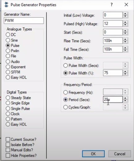
- To provide, Pulse width modulation signal to MOSFET, we used a PWM generator signal of proteus,
- Now place all components in the proteus window, and make a connection according to this circuit diagram.
- Now open, PWM signal, and make setting according to these values.
- After that connect the output voltage probe, and output current probe.
- Now add analog graphs, to check waveforms of output current and voltage.
- In order to check output voltage waveform, right-click on graph, and make starting and end time settings.
- After that simulate the graph.
- As you can see from the graph, output voltage first shoots up, and after some time settles to 16 volts output.
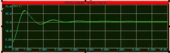
Not that, while designing a boost converter practically, we can remove these starting output voltage fluctuations, by using a PID controller.
After that, follow the same procedure to see the output current waveform.
As you can see, the output current is continuous. This is how we can simulate a boost converter in proteus.
You may also read:
- Boost Converter using Pic Microcontroller
- Buck Converter using pic microcontroller
- Single Phase to Single Phase Cycloconverter Design Using Simulink
- Buck-Boost converter with pic microcontroller and ir2110
- output inductor design and calculation for SMPS
- FREQUENCY TO VOLTAGE CONVERTER CIRCUITS
- Buck converter simulation using PSpice
- LM2576 3-Ampere Step-Down Voltage Regulator
- How to design a snubber circuit?
- what is the gate driver circuit?
I wants same explanation as u have been given in DC boost converter about the experiment on MOSFET CS amplifier Transfer characteristics woth DC load line to calculate Q point or DC operating point