CONTROLLER AREA NETWORK (CAN): Let’s start with the INTRODUCTION of controller area network. The acronym for CAN is controller area network which comes from the family of ISO 11898. CAN is an extremely robust serial communication protocol because it detects an error in the messages and it also sends acknowledgment messages for communication. Hence it is messages based not address based. The peer-to-peer or master-to-slave style of communications allowed in the CAN network by distributing control. It is more flexible and efficient network.
HISTORY of controller Area network
The first release of the CAN protocol came in 1985 by Robert Bosch. He originally developed and released CAN to meet the requirements of automotive network and reduces the cost and size of vehicle wiring harness. The ISO standardized CAN in the early 1990s in ISO-11898. Further in 1995 ISO released an extended version of CAN which introduced the amendment in frame format known as CAN 2.0B. In 1995 many higher layer protocols (HLPs) were introduced the market and standardized in CAN. The automotive OEMs started their development of propriety in CAN HLPs. The CANopen also created by CIA standardized by using CAN in this year. In 2000 Society of Automotive Engineers (SAE) published SAE-J1939. Nowadays CAN is found in almost every market but still, development is continuing in the area of HLPs to meet the requirements and needs of existing and new developers.
NETWORK MODEL of controller area network
The figures show the OSI seven layers model. This model is the reference model for developers to define the network into different layers.It can be observed from the fig:02 that only two layers include the CAN network as compared to OSI. The data link layer and a physical layer which includes the error detection and data flow. The upper layers in the OSI are the HLP in the CAN network.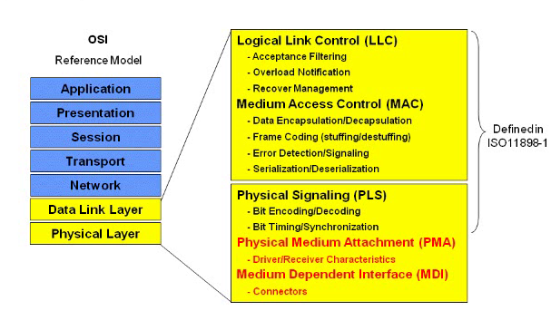
FIGURE 1 OSI LAYERS WITH CAN LAYERS
CAN PHYSICAL NETWORK
The figure shows the simple network of CAN. This network comprises of four nodes connected via the physical layer. The transmission speed is defined 1Mbps to the bust line. The door node works as the transmitting and receiving just like simple door works. The nodes check the messages as these messages are broadcast. If all nodes clear the messages then acknowledgment from sender to receiver. If one node discards the message like engine node then there are two methods to recover. The first is to notify the transmitter and second is the usage of different filtering methods.
FIGURE 2 PHYSICAL NETWORK
TYPES OF NODES in controller area network
There are various types of nodes found in the CAN network. The figure shows the three types of nodes used in microcontroller integrated CAN network. It requires faster communication between CAN network and microcontroller. The third is the CAN is the extender node. It does not use with microcontroller but It has flexibility and can be used with other two nodes. This model is designed for low cost, simple and also used for very complex applications.
FIGURE 3 TYPES OF NODES
CAN FRAMES
There are various frames in CAN network described below.
DATA FRAME in controller area network
There are two frames standard and extended shown in below figure. The standard h11-bit 11-bit identifier while extended has a 29-bit identifier. There is a bit reserved for start and end of a frame. After that there ID which means that it gives the id number to each message according to the priorities. All the fields check the messages for any error. The control field has ID bit showing that either it is standard or extended or DLC (data link control) bit which denotes the data. The next field is the data where actual data has to fit. After that finally, it is CRC (cyclic redundancy check) for error detection. The acknowledgment field which is at the receiver for sending an acknowledgment to the transmitter.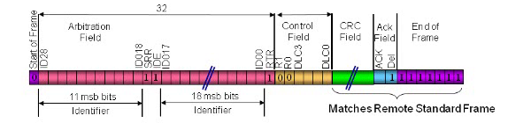
FIGURE 4 11-BIT IDENTIFIER FILED (STANDARD)
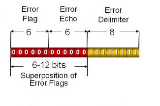 FIGURE 5 29-BIT IDENTIFIER (EXTENDED)
REMOTE DATA FRAME
The Remote data frames used for higher priorities protocols. It also has standard and extended frames size but it does not include the data field as it is used for control.
FIGURE 6 11-BIT IDENTIFIER FIELD (STANDARD)
 FIGURE 7 29-BIT IDENTIFIER FIELD (EXTENDED)
ERROR FRAME
If the data is in the active state then it has active error frame and if it has passive state then it has passive error frame. It might that CRC result may be wrong or byte stuffing may produce error so we sent the error frames. The frame has error flag for an indication for error frame, error echo for sound and error delimiter.
FIGURE 8 ACTIVE ERROR FRAME
 FIGURE 9 PASSIVE ERROR FRAME
OVERLOAD FRAME
The overload frame is used when there is a delay in the data and retransmission for messages. If the nodes need more processing at the protocol level it has the ability to transmit two more nodes.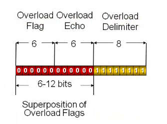
FIGURE 10 OVERLOAD FRAME
CSMA/CD-CR
It is the acronym of Carrier Sense Multiple Access and Collision Detection with Collision Resolution.
- CARRIER SENSE (CS): In this, every node must monitor the bus for a period of no activity before sending a message. It is used when there is error free transmission.
- MULTIPLE ACCESS (MA): Once a period of no activity occurs, every node has an equal opportunity to transmit a message. It is used at the start of every frame.
- COLLISION DETECTION (CD): If 2 nodes transmit at the same time, a collision occurs.
- COLLISION RESOLUTION (CR): It is nondestructive bitwise arbitration. In simple words, it means that the messages remain intact even after a collision occurs.
All arbitration takes place without corruption or delay of the highest priority message. The main thing to implement CSMA/CD-CR is that the physical layer must be dynamically arbitration bit streams. It means the message which losses the CAN BUS in arbitration is automatically retransmitted at the next available time. The below figure shows the two nodes of transmitter and receiver CAN. The starting pulse shows the start of a frame at node 1 and node 2. After that transmission occurs and at node there is an error of lost arbitration but there is no error in node 2. Each node has its oscillator and internal clock. Here one question comes in mind that how synchronization occurs? The receivers synchronize on recessive to dominant transitions. The hard synchronization produces at SOF(start of frame) and resets bit clock. The resynchronization produces at recessive-to-dominant (1-to-0) edges and it adjusts the bit clock as most important.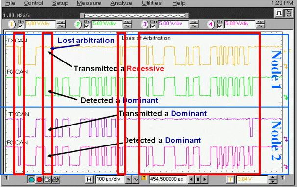
FIGURE 11 PROCESS OF CSMA/CD-CR
 FIGURE 12 SYNCHRONIZATION
BIT STUFFING in controller area network
It is used to maintain the synchronization. It ensures recessive to dominant edges. The bit which is to be stuffed after 5 bits in a row(recessive or dominant).The bit is added at the transmitter side and removes at the receiver side.
FIGURE 13 BIT STUFFING
ERROR HANDLING
There are several different types of error conditions defined to control the errors in the CAN protocol. It requires sending error frames at transmitter and receiver. It ensures the integrity of messages. The CAN nodes can make immediate transition from working normal state to being disconnected from the network based on faulty data. The faulty confinement prevents faulty nodes from continuously transmitting and bogging down a network.
CRC ERROR
The 15 bits CRC appended in CRC filed. All nodes receive message, measures CRC and verify against CRC received. If both CRCs do not match, then a CRC error occurs and an error frame is generated. After that the transmitting node sees and error occur and retransmits the original message in the next available time.
FIGURE 14 CRC ERROR
ACKNOWLEDGEMENT ERROR
The transmitting nodes check the ACK slot bit which it has sent as a recessive and check for a dominant. If dominant bit occurs, at least one node received the message correctly. If not then ACK error occurs an error frame is generated and the message will be retransmitted.
FIGURE 15 ACKNOWLEDGEMENT ERROR
FORM ERROR
The node which detects a dominant in the CRC Delimiter, ACK Delimiter, End of Frame field or interference Space generates an error frame for form error. Now the original messages will be retransmitted.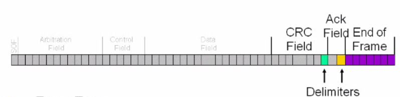
FIGURE 16 FORM ERROR
STUFF ERROR
If 6 consecutive bits with the same polarity are detected between the SOF (start of frame) and the CRC Delimiter, the rule of bit stuffing has been violated. In this condition an error frame is sent and the message will then retransmitted.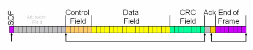
FIGURE 17 STUFF ERROR
BIT ERROR
It produces when the transmitter monitors a signal on the bus which is opposite of what it sent. Now error frame is sent and the original message is repeated.
FIGURE 18 BIT ERROR
RECOVERY FROM BUS OFF
There are two techniques to recover. The first one is the change into configuration mode. The second is to detect 128 occurrences of 11 consecutive recessive bits like long bus idle or 128 valid messages or a combination of both. The below diagram shows the recovery.
FIGURE 19 RECOVERY FROM BUS OFF
FAULT CONFINEMENT
There are three error states defined by CAN as a function of the error counters: error active, error passive and bus-off. The normal mode is the error active in which it is allowed to send messages and active error frames. The warning interrupt occurs when either error counter exceeds 95. The node becomes error passive when either error counter exceeds 127 in which it can transmit and receive data messages but transmit only passive error frames. Now when transmit error counter exceeds 255 nodes comes into bus off. In this modes, it cannot transmit anything on the bus.The only transmit error counter can cause “bus off”.
FIGURE 20 FAULT CONFINEMENT
TRANSMITTING A CAN MESSAGE
First node has to be in configuration mode and then after it initlaizes.then it has to load the transmit request bit. Then after the bit stffing and error frame checking occurs.The below block digram can be observed explaining the whole process.
FIGURE 21 TRANSMISSION PROCESS
RECEIVING A CAN MESSAGE
Firstly the node has to be in the normal mode to receive the CAN message and then it filters the error when the message received. The de-stuff the bits and checks the errors. The below diagram shows the receiving process.
FIGURE 22 RECEPTION PROCESS
The transmitting and receiving a CAN message is not a difficult task but it is handled by protocol engine in the CAN module. To transmit a message it typically requires loading the Identifier, DLC, and Data, and then setting the “Transmit-Request” bit. The receiving a message requires monitoring “Receive Buffer Full” bit with polling or using interrupts to give notifications to user application when a CAN message received.
CONCLUSION about controller area network
The articles conclude the discussion about the basics of CAN and which things make it a robust data communication protocol. The basic operation of transmitting and receiving a CAN message from a PIC microcontroller has been described and explained. The CAN protocol is mostly applicable for low-level hardware which minimizes software overhead.
i want can based communication project(pic16877a to pic16f877a)