CD4017 is a Johnson 10 stage CMOS Decade counter IC. W can use it for low range counting applications. It is a 16-pin counter that can count from 0 to 10 by turning on the 10 outputs one by one on every positive edge of a clock. The circuit consists of CD4017 will save board space and also the time required to design the circuit. We can reset and control counting with the help of reset and enable pins.
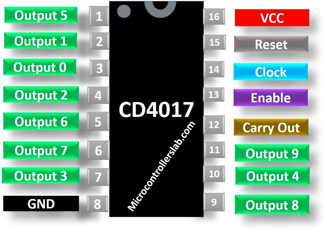
CD4017 Pinout diagram
This picture shows a pinout diagram of CD4017 counter. It consists of 16 pins. 11 pins are output pins. 5 pins are of power supply and control pins.
Pin Configuration Description
In this section, we descibes the details of CD4017 pins.
| Pin Number | Pin Name | Description |
|---|---|---|
| 1 | Output 5 | When the value of counts is 5, it gets HIGH |
| 2 | Output 1 | When the value of counts is 1, it gets HIGH |
| 3 | Output 0 | When the value of counts is 0, it gets HIGH |
| 4 | Output 2 | When the value of counts is 2, it gets HIGH |
| 5 | Output 6 | When the value of counts is 6, it gets HIGH |
| 6 | Output 7 | When the value of counts is 7, it gets HIGH |
| 7 | Output 3 | When the value of counts is 1, it gets HIGH |
| 8 | GND | Make connection to the ground of the circuit. |
| 9 | Output 8 | When the value of counts is 8, it gets HIGH |
| 10 | Output 4 | When the value of counts is 4, it gets HIGH |
| 11 | Output 9 | When the value of counts is 9, it gets HIGH |
| 12 | CARRY-OUT | This pin goes HIGH, when the counts exceed 10 and useful for cascading IC’s. |
| 13 | ENABLE | The enable pin is active low. When it is high, the circuit will not receive clock signals and the counter will not count. |
| 14 | CLOCK | This is the clock input signal. On every positive edge of a clock, counter value gets increment by 1. |
| 15 | RESET | restart the counter from 0. |
| 16 | Vcc | It is connected to the positive supply |
CD4017 Electrical Features
- High operating frequency 16 pin CMOS Decade counter
- Decoded outputs pins = 10
- Clock input is Schmitt triggered which provides pulse shaping and therefore it has no rise and fall times limitation.
- The voltage supply range is from 3V to 15V but in normal operation, +5V is used.
- CD4017 is TTL compatible
- It has a medium operational speed which is typically 5MHz and the maximum clock frequency is 5.5Mhz
- Multiple 16-pin packages PDIP, GDIP, PDSO packages
Other Equivalents
CD4040, CD4060, CD4022, CD4026, CD4020, CD40103, CD4017, 74LS90, 74LS93
Where to use it?
As this CD4017 is a 5-stage decade counter. Therefore its most basic use is in counting applications. It can turn on its 10 outputs sequentially according to time and frequency at CLK input pin. This is commonly used in projects used for LED chasers for example LED sequencer. In this project, the decade counter IC increments the counter value on every clock pulse and the output pins gets high one by one. LED’s are connected to these outputs which glows in a sequential pattern. CD4017 IC is best for projects that require a sequential counting pattern.
How to use CD4017?
CD4017 has 10 output pins that gets HIGH in a sequential pattern when clock signal is applied. This clock signal can be generated through 555 timer IC or any other digital IC’s. Pin 13 which is clock enable pin is kept LOW otherwise it can halt the clock signal. The Reset Pin is also kept LOW. This pin is responsible for resetting the counter to restart the counting from 0. Therefore, for normal operation of a circuit, these two pins are kept LOW.
Timing Diagram
We can increase the counting to 20 by cascading two IC’s. Similarly, this range can be increased to 30, 40, …, 10N numbers. The cascading is done by Carry Out pin which is LOW by default but when the counts reaches 10, this pin gets HIGH. It will remain HIGH for 5 counts then will go down to 0 volts. When the count reaches 10, it will go HIGH again. The timing diagram indicating the behavior of all the outputs on different inputs is given below:

Example Circuits
In this section, we will see some example circuit using CD4017 Counter.
Simple LED Chaser Example
In this example, we use a LED bargraph that consists of ten light emitting diodes. Therefore, we will display output of counter on LED bargraph. As we mentioned earlier, output pins Q0-Q9 give logic high signal sequentially. Output transition occurs on every positive edge of clock cycle.

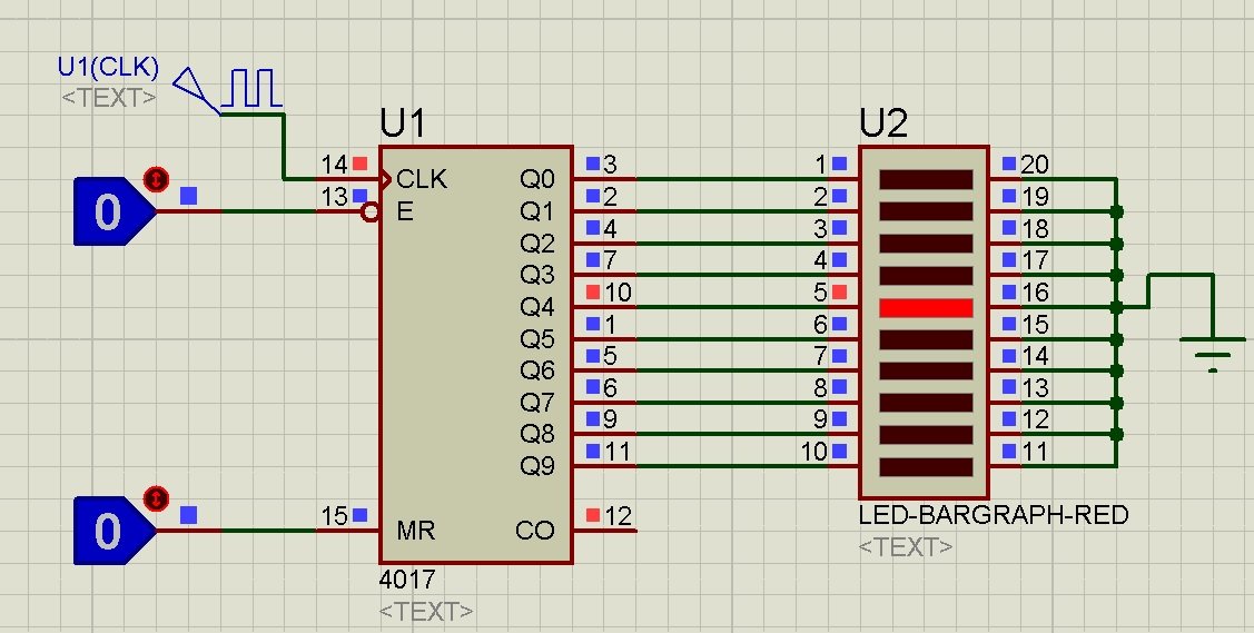
The rate of output change depends on clock frequency. The maximum operating frequency which CD4017 supports is 10MHz. Further, we can control output with the help of Enable pin. For example, if input to enable pin is active high, output will halt. Therefore output will not change even on positive clock edge. Additionally, if you want to reset the output, MR pin can restart the counting.
Example with LED
In this example circuit, we use LEDs instead of bargraph.

Example with 555 Timer
This is a complete and practical circuit diagram for a LED flasher. We will provide clock signal through 555 timer IC.
Proteus Simulation
CD4017 Applications
- LED matrix circuits
- LED chaser applications and LED based projects
- Binary counter or Binary decoder
- Divisiable counting by N
- Industrial and medical electronics.
Thanks for you. it help me so much to understand about CD4017 IC.
I’ve used it in 27 MHz applications for relatively high precision clocks. I’ve not tried it, but I think it can be pushed a little further.
thanks for the info, the working voltage range is 3 to 15 V , does the 4017work better at say 5V or will it work better at a higher voltage ? , say 9 or 12 ????