The DAC0808 IC is a monolithic digital to analog converter which takes an 8-bit digital data as an input and sends an analog signal at the output. It has high accuracy and utilizes very low power. Electronic devices like music players, televisions, mobiles, CD players gaming systems, etc. use this chip for the conversion of audio signals. This article discusses in detail the working, Pinout configuration, Proteus simulation and uses of IC DAC0808.
Why We need DAC0808 IC?
In the real world, most of the data is in the form of analog signals. Therefore, we need a device that can perform digital to analog conversion. For example, a microphone takes an analog audio signal as an input which is converted into a digital signal so that the computer can process it by adding effects and removing noise. Now, if you want to run a speaker, we need to convert this digital signal back to an analog signal. For this purpose, we need DAC0808 DAC’s which are basically digital-to-analog converters.
Pinout Diagram
As you can depict from DAC0808 pinout diagram that it consists of 16 pins. Eight pins are digital input pins and IOUT is an analog output pin along with Vref+ and Vref- used to set a reference point for analog output. We will see in Proteus simulation about how to set these parameters.

Pin Configuration Description
This table contains pin configuration details of DAC0808 digital to analog converter IC.
| Pin Number | Pin Name | Function |
| 1 | NC | No Connection that means not used |
| 2 | GND | Power supply ground terminal |
| 3 | VEE | Used for external compensation capacitor connection between VEE and Comp pins |
| 4 | IOUT | input/output terminal for analog signal |
| 5-12 | MSB A1 – LSB A8 | These are the eight bits of DAC0808 input. A1 is the first bit or MSB of that input and A8 is the least significant bit of input applied |
| 13 | Vcc | Positive Power supply |
| 14 | VREF+ | Positive reference voltage |
| 15 | VREF- | Negative Reference voltage |
| 16 | Compensation | COMP is a compensation pin for DAC where we connect an external capacitor |
Features
The DAC0808 IC has following specifications:
- It has a parallel digital input that takes 8-bit data and gives output with relative accuracy at the highest error of ±0.19%.
- The power supply used should be in a range of ±4.5V to ±18V.
- The settling time is 150 ns which is very fast.
- DAC0808 provides features of low power consumption. The maximum power it can dissipate is 1000mW. For a supply voltage of ±5V, it utilizes only 33 mW power.
- The inputs are CMOS and TTL compatible.
- This DAC IC has a high-speed input slew rate of 8 mA/μs.
- It works within a range of 0°C to +75°C temperature.
- It is a direct replacement of MC1508/MC1408 IC’s.
Where and how to use DAC0808?
Due to the advancement in technology, there are microcontrollers available with built-in ADC’s or DAC’s. That’s why we use this IC’s in beginner level applications. We use this IC generally for Digital to Analog Conversions. It takes parallel input in the form of 8-bits. The DAC0808 chip converts this digital input into a current (). We convert this current into an analog voltage by connecting a resistor at the output. The figure below shows a simple circuit which uses DAC0808.
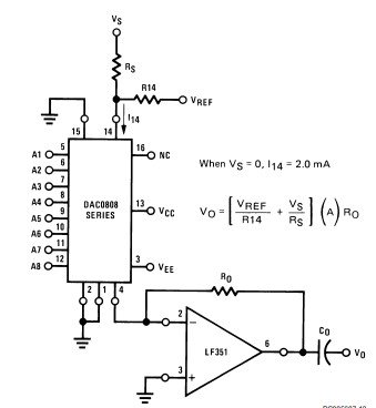
We can apply 8-bit digital input to DAC0808 digital inputs pins through any microcontroller like 8051 or PIC etc. The IC changes this input into a current. We have connected an LF351 operational amplifier to convert this current to voltage. The output voltage obtained through LM351 IC is linearly proportional to the digital inputs. The above circuit is also known as the current to voltage converter as it is converting a current to an analog voltage.
Example Circuit
In this example circuit, we designed a circuit that generates an analog voltage output between 0-10 volts.
How to apply 8-bit digital Input
In order to provide an 8-bit digital input signal to DAC0808, we used two 74LS393 counter ICs. This is a 4-bit counter IC but we need 8-bit input data. Therefore, we connected two 74LS93 counter ICs in cascading. Now output pins of these counters will count from 00000000-11111111. In other words, the digital input data to the DAC IC will be in the range of 00000000-11111111.
- When we apply 00000000 digital signal to input pins of DAC0808, it will generate zero analog voltage at the output pin (IOUT).
- The maximum output voltage will appear on the IOUT pin when we apply 11111111 input.
How to use Reference voltage?
Reference voltage defines the output voltage range of analog output signal from op-amp output. Pin14 and Pin15 are Vref- and Vref- pins respectively that are used to set reference voltage of output signal. For example, in this circuit, we used a +10 volts reference voltage by connecting +10 volts to Vref+ and Vref- pins. In a similar way, we can set any reference voltage within a specified limit according to the datasheet.
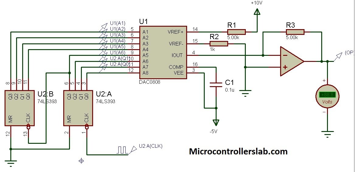
How does it work?
DAC0808 IC takes 8-bit input data from two 74LS393 counter ICs. The clock signal connected with counters ICs changes counter value from 0,1,2… and to a maximum value on every positive edge of the clock cycle. Digital to analog converter IC converts this input data into analog output voltage.
The output signal magnitude is directly proportional to 8-bit input signal and reference voltage value. However, as you know that reference voltage will be constant for most of the time like in the above example circuit. Hence, output signal magnitude mainly depends on 8-bit digital input to the DAC IC.
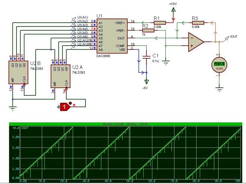
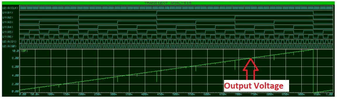
Proteus Simulation Graph
This graph shows the simulation result ( transient analysis) of the above-given circuit. As you can see from this proteus simulation graph, voltage is changing linearly from 0 to a maximum voltage of 10 volts according to the 8-digit input signal. Input signal changes on every positive edge of a clock cycle.
DAC0808 Applications
In addition to Digital to Analog Conversion, some other applications of DAC0808 are:
- radar systems
- military test equipment
- Audio conversion in microphone or headphones
- sampling oscilloscopes
- Electrical measurements
- Sample and Hold circuits
- high-speed integrators
- Music players, television, speakers, CD players
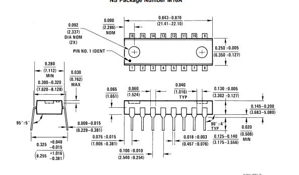
DAC IC 2D Diagram