In this user guide, we will show you how to design a digital ohmmeter using pic microcontroller. A digital ohmmeter is used to measure the resistance of any resistor or any circuit. It can measure resistance between 0-1MΩ with a precision of ±5%. PIC16F877A microcontroller is used in this project to measure resistance by doing signal conditioning of measured resistance.
Analog and digital ohmmeter
An analog ohm meter uses electronics concepts to measure resistance and displays it on analog meters with the help of needles. On the other hand, a digital ohmmeter uses numerical display to display resistance value like seven segment display, liquid crystal display and LED displays. Digital ohmmeter also uses digital electronics to measure resistance with the help of microcomputers.
Digital ohmmeter Circuit diagram using pic microcontroller
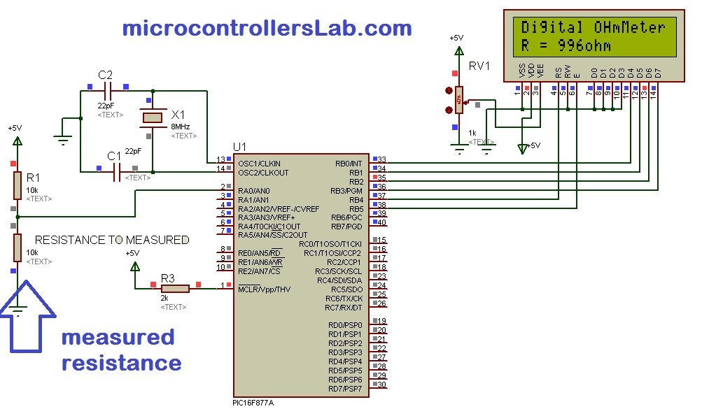
The diagram below shows the circuit of digital ohmmeter using pic microcontroller. As shown in figure below, resistance R1 is pulled with 5 volt source and resistance whose value we want to measure is connected with ground and other terminal of resistance R1. Voltage divider concept is used to measure the resistance value. An LCD is used to display the value of the resistance in ohm.
Digital ohmmeter working and operation
In above circuit diagram resistance R1 is used to as pull up resistor. Resistance R1 is connected to 5 volt source. The resistance whose value we want to measure is connected with resistance R1 to form a voltage divider. In a previous Digital voltmeter article, we discussed how to measure voltage using pic microcontroller whereby a voltage divider was used to design the digital voltmeter. We have used the same concept here to design the ohmmeter.
Voltage across measured resistance is calculated with the help of PIC16F877A microcontroller. Voltage across measured resistance value is measured with channel ANO of PIC16F877A microcontroller. Now the question is how resistance can be determined by using measured value of voltage? It is very easy to calculate using voltage division formula. Voltage divider formula is given below:
Voltage Output = (measured resistance/ (measured resistance + R1)) * Vcc
Value of Vcc and resistance R1 is known, where is Vcc = 5 volt and R1 = 10K ohm. So, PIC16F877A microcontroller calculates the Voltage Output according to connected measured resistance value. After that measured resistance value can be easily calculated by using below given formula:
Measured resistance = R1 × Voltage Output / 5 – Voltage Output;
Therefore measured resistance = 10000 × Voltage Output / 5 – Voltage Output;
The formula above is just the rearranged form of the voltage division formula. Hence, the resistance can be easily calculated by using above calculations in programming.
Note: This digital ohmmeter can measure resistance between 0-1M ohm with precision of ±5 percent.
Additionally, we are using a 16×2 LCD to display the resistance values. If you don’t know about voltage measurement and LCD interfacing with pic microcontroller, follow the recommended readings below:
Digital Ohmmeter with Pic Microcontroller Code
The program code for digital ohmmeter using pic microcontroller is written in mikroC PRO compiler.
Make sure to tick the following system libraries found in the Library Manager before compiling the code:
- ADC
- Conversions
- Lcd
- Lcd_Constants
sbit LCD_RS at RB4_bit;
sbit LCD_EN at RB5_bit;
sbit LCD_D4 at RB0_bit;
sbit LCD_D5 at RB1_bit;
sbit LCD_D6 at RB2_bit;
sbit LCD_D7 at RB3_bit;

sbit LCD_RS_Direction at TRISB4_bit;
sbit LCD_EN_Direction at TRISB5_bit;
sbit LCD_D4_Direction at TRISB0_bit;
sbit LCD_D5_Direction at TRISB1_bit;
sbit LCD_D6_Direction at TRISB2_bit;
sbit LCD_D7_Direction at TRISB3_bit;

float resistance = 0.0;
const float Vcc = 5.0;
char ohm[4];

void main() {

     PORTA = 0;
     TRISA = 0X01;
     PORTB = 0;
     TRISB = 0;
     Lcd_Init();
     ADC_Init();
     Lcd_Cmd(_LCD_CURSOR_OFF);
     Lcd_Cmd(_LCD_CLEAR);
     Lcd_Out(1,1,"Digital OHmMeter");
     delay_ms(1000);
     while (1)
     {
        resistance = ADC_Read(0);
        resistance = ((float)(resistance))*0.0048828;
        resistance = (unsigned long)((resistance*1000)/(Vcc-resistance));
        inttostr(resistance,ohm);
        Lcd_Out(2,1,"R = ");
        Lcd_Out(2,5,Ltrim(ohm));
        Lcd_Out(2,8,"ohm");

     }
 }
How does the Code Work?
We will start off by defining the pic microcontroller’s PORTB connections with the LCD.
sbit LCD_RS at RB4_bit;
sbit LCD_EN at RB5_bit;
sbit LCD_D4 at RB0_bit;
sbit LCD_D5 at RB1_bit;
sbit LCD_D6 at RB2_bit;
sbit LCD_D7 at RB3_bit;
Next we will specify the directions of the pins:
sbit LCD_RS_Direction at TRISB4_bit;
sbit LCD_EN_Direction at TRISB5_bit;
sbit LCD_D4_Direction at TRISB0_bit;
sbit LCD_D5_Direction at TRISB1_bit;
sbit LCD_D6_Direction at TRISB2_bit;
sbit LCD_D7_Direction at TRISB3_bit;
Create a float variable ‘resistance’ to hold the measured resistance values. Initially, it holds the value 0.
float resistance = 0.0;
Likewise, create a const float variable ‘Vcc’ that will store the value 5.
const float Vcc = 5.0;Create a char array ‘ohm’ of size 4.
char ohm[4];Inside the main() function, we always initialize variables, define GPIO pins settings and peripherals initialization.
     PORTA = 0;
     TRISA = 0X01;
     PORTB = 0;
     TRISB = 0;
Initialize the LCD module and the ADC module.
     Lcd_Init();
     ADC_Init();
Next, we will send commands to the LCD to turn the cursor off and clear the screen.
 Lcd_Cmd(_LCD_CURSOR_OFF);
 Lcd_Cmd(_LCD_CLEAR);
Using Lcd_Out(), we will print the text ‘Digital OHmMeter’ at starting position row=1 and starting position column=1.
Lcd_Out(1,1,"Digital OHmMeter");Next we will find the ADC value at channel 0 using ADC_Read(0) and save it in the variable ‘resistance.’ Next we will perform some calculations (voltage divider formula mentioned previously) to find the measured resistance value and convert it to string.
- resistance = ((float)(resistance))* 0.0048828 : It converts ADC binary value back into voltage output value. Note here 0.0048828 is 5/1023.
- resistance = (unsigned long)((resistance * 1000)/(Vcc – resistance)) : This statement converts output voltage of ADC into measured resistance value by using voltage divider formula
- inttostr(resistance,ohm) : It converts resistance value into string to display it on LCD
        resistance = ADC_Read(0);
        resistance = ((float)(resistance))*0.0048828;
        resistance = (unsigned long)((resistance*1000)/(Vcc-resistance));
        inttostr(resistance,ohm);
Consequently, print the value of resistance with its unit on the LCD screen using Lcd_Out() and specifying the starting row, starting column and text as parameters inside it.
        Lcd_Out(2,1,"R = ");
        Lcd_Out(2,5,Ltrim(ohm));
        Lcd_Out(2,8,"ohm");
You may also like to read:
- Digital AC voltmeter project
- Voltage Sensor Module Interfacing with Arduino – DC Voltage Measurement
- Digital AC Ammeter project
- AC Voltage Measurement using Arduino – Difference Amplifier Technique
- Digital DC voltmeter project
- Three phase voltage measurement using pic microcontroller
- Digital DC Ammeter project
- Digital DC watt meter using pic microcontroller
- Digital watt meter using pic microcontroller
Good day sir. There’s some error I’ve experienced in coding in the line resistance = ADC_Read(0): It says error “assigning to non-lvalue ‘resistance’ What should I do with it?
Good day sir, Thank you for sharing this digital ohmmeter circuit with us. I try to understand the program.
There’s something thing i wanna ask you about the formula that you use.
The resistance coding
resistance = ADC_Read(0);
resistance = ((float)(resistance))* 0.0048828;
resistance = (unsigned long)((resistance * 1000)/(Vcc – resistance));
1. How you get the numbers of 0.0048828?
2.How you manipulated the voltage divider formula to write formula in programming?
Thank you sir,
have you replaied any answer ??!
0.0048828 is from ADC -> where you have: ADC(value ) * 5 / 1023, and 5/1023 = 0.0048828
Digital Ohmmeter
Good day sir,
Can you send me by e-mail the file “.HEX ”
Thank you
Jimmy
Its 5/1024=0.000488
5v from vref+ and 1024 possible values for de A/d converter (10bit converter 2^10)
Hi,
resistance = (unsigned long)((resistance * 1000)/(Vcc – resistance)) :
I think this equation is wrong, instead of 1000 use 10000.
Which type of potentiometer did you use? Proteus shows 3 different ones with same appearence.
you can use anyone with active status for simulation in proteus
Hello.
I almost done the project but I can’t figure out the cod for the ADC converter, especially the ADC_Init file. Could you please how us the code in that file?
Thank you!!!
Thanks you very much for this please can you help me the list of components needed to implement this sir, and also the hex file if you don’t mind.
Hi sir!
We have a question. We couldnt run this code in MPLAB. we need a solition for our project. please help us immediately. Thanks for your help kind sir.