In this tutorial, we will show you how to design a digital Ammeter circuit using pic microcontroller to measure dc current. By the end of this project you will be able to:
- Measure dc current using pic microcontroller
- Convert current into voltage using a shunt resistor
- Design low resistance shunt resistor using a simple wire
- Display the dc current value on an LCD.
The digital ammeter circuit has many applications in electronics, electrical, and power electronics projects. Current measurement is also used in microcontroller-based projects for over-current protection in circuits. Other than this application, it can be used as a digital Ammeter circuit for current measurement in electronics experiments.
Circuit diagram of digital ammeter circuit using pic microcontroller
A circuit diagram of a digital Ammeter circuit using pic microcontroller is given below. In this circuit diagram, a 30V dc source is applied to a 40ohm load. Current passing through this load is measured with the help of a shunt resistor and PIC16F877A microcontroller.
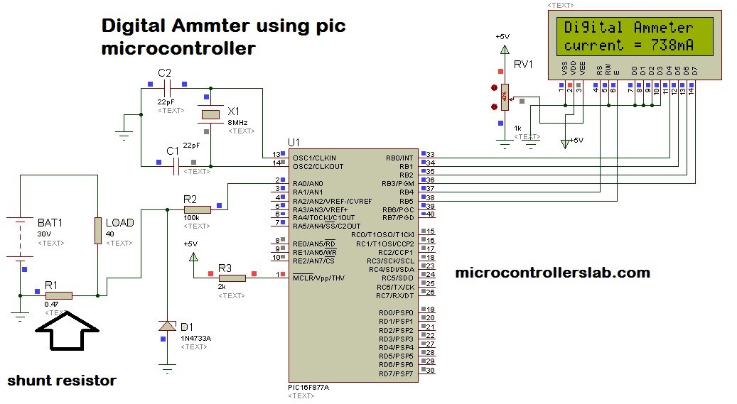
100K ohm resistor at the input of analog to digital converter is used to protect microcontroller from high current. This is because the current always follows a low resistance path. If you don’t use any resistor there, the current will start to flow towards the microcontroller instead of the shunt resistor. It will damage microcontroller permanently.1N4733A Zener diode is used to protect microcontroller from over voltage appearing across it. This is because voltage greater than 5 volts may damage microcontroller permanently. LCD is interfaced with the PIC16F877A microcontroller to display current value.
If you don’t know how to interface LCD with the PIC16F877A microcontroller, check following article first:
Why do we need a shunt resistor?
Microcontrollers or any microcomputer system can not read current directly. They only sense voltage. Microcontrollers logic high and low is also based on the voltage level. Therefore, microcontrollers do not sense current directly. That is why we need to find current into voltage form. The Shunt resistor is used to convert current into voltage form. When current passes through the shunt resistor, voltage appears across shunt resistor. This voltage can be easily measured with the help of analog to digital converter channel of PIC16F877A microcontroller. This measured voltage value can be converted back into current in programming using ohm’s law formula:
V = IR;
Shunt resistor value is known and voltage is measured with pic microcontroller. So current can be easily calculated by using above Ohm’s law formula.
I = V/R
In this digital ammeter circuit project, 0.47 ohm shunt resistor is used. Now you must be wondering how to design this low resistance value resistor? The simplest solution to this problem is to take a piece of wire and turn it a few times. After making few turns, measure its resistance with the help of ohm meter. You can easily design .47 ohm resistor with the help of simple wire. It is a hit and trial method. Keep trying until you successfully get a value close to .47 ohm. Other option is to use hall effect current sensor which converts current into voltage directly. Magnitude of voltage depends on magnitude of current.
Digital Ammeter with pic microcontroller Code
Now lets discuss how to write code for digital ammeter using pic microcontroller. The program code for digital Ammeter is written using mikroC PRO compiler for pic. It is very easy to use to compiler for pic microcontroller. It have large set of libraries which makes microchip microcontroller very easy to use.
Make sure to tick the following system libraries found in the Library Manager before compiling the code:
- ADC
- Conversions
- Lcd
- Lcd_Constants
sbit LCD_RS at RB4_bit;
sbit LCD_EN at RB5_bit;
sbit LCD_D4 at RB0_bit;
sbit LCD_D5 at RB1_bit;
sbit LCD_D6 at RB2_bit;
sbit LCD_D7 at RB3_bit;

sbit LCD_RS_Direction at TRISB4_bit;
sbit LCD_EN_Direction at TRISB5_bit;
sbit LCD_D4_Direction at TRISB0_bit;
sbit LCD_D5_Direction at TRISB1_bit;
sbit LCD_D6_Direction at TRISB2_bit;
sbit LCD_D7_Direction at TRISB3_bit;

float current;
char curr[4];

void main() {

     PORTA = 0;
     TRISA = 0X01;
     PORTB = 0;
     TRISB = 0;
     Lcd_Init();
     ADC_Init();
     Lcd_Cmd(_LCD_CURSOR_OFF);
     Lcd_Cmd(_LCD_CLEAR);
     Lcd_Out(1,1,"Digital Ammeter");
     delay_ms(1000);
     while (1)
     {
        current = ADC_Read(0);
        current = (current * 4.89)/0.47;
        inttostr(current,curr);
        Lcd_Out(2,1,"current = ");
        Lcd_Out(2,11,Ltrim(curr));
        Lcd_Out(2,14,"mA");

     }
 }
How does the Code Work?
We will start off by defining the pic microcontroller’s PORTB connections with the LCD. PORTB is used to send data to LCD. These lines tell the microcontroller that LCD is connected to PORTB pins and these lines also specified the pin numbers as shown below:
sbit LCD_RS at RB4_bit;
sbit LCD_EN at RB5_bit;
sbit LCD_D4 at RB0_bit;
sbit LCD_D5 at RB1_bit;
sbit LCD_D6 at RB2_bit;
sbit LCD_D7 at RB3_bit;
Next, we will specify the directions of the pins:
sbit LCD_RS_Direction at TRISB4_bit;
sbit LCD_EN_Direction at TRISB5_bit;
sbit LCD_D4_Direction at TRISB0_bit;
sbit LCD_D5_Direction at TRISB1_bit;
sbit LCD_D6_Direction at TRISB2_bit;
sbit LCD_D7_Direction at TRISB3_bit;
Create a float variable ‘current’ to hold the dc current values.
float current;Create a char array ‘curr’ of size 4.
char curr[4];Inside the main() function, we always initialize variables, define GPIO pins settings and peripherals initialization.
In this code TRISA is used to define port A as input because voltage is measured with pin number AN0 of port A. TRISB instructions defines PORTB as an output PORT. It is used to send data to LCD.
     PORTA = 0;
     TRISA = 0X01;
     PORTB = 0;
     TRISB = 0;
Initialize the LCD module using LCD_Init() funtion and the ADC module using ADC_Init().
     Lcd_Init();
     ADC_Init();
Next, we will send commands to the LCD to turn the cursor off and clear the screen.
 Lcd_Cmd(_LCD_CURSOR_OFF);
 Lcd_Cmd(_LCD_CLEAR);
Using Lcd_Out(), we will print the text ‘Digital Ammeter’ at starting position row=1 and starting position column=1.
Lcd_Out(1,1,"Digital Ammeter");Next we will find the ADC value at channel 0 using ADC_Read(0) and save it in the variable ‘current.’ This is the voltage across the shunt resistor. To find the dc current, we will use the ohm’s law to convert the voltage reading to current. Lastly, we convert this value to a string in order to print it on the LCD.
- current = (current * 4.89)/0.47: This statement converts output voltage of ADC to current value by using ohm’s law formula.
- inttostr(current,curr) : It converts the dc current value into string to display it on the LCD.
current = ADC_Read(0);
current = (current * 4.89)/0.47;
inttostr(current,curr);
Consequently, print the value of current with its unit on the LCD screen using Lcd_Out() and specifying the starting row, starting column and text as parameters inside it.
        Lcd_Out(2,1,"current = ");
        Lcd_Out(2,11,Ltrim(curr));
        Lcd_Out(2,14,"mA");
Conclusion
This is all about digital ammeter circuit using pic microcontroller project, circuit diagram and coding. If you feel any issues while designing your digital ammeter circuit, feel free to comment on this post. You may also check the following articles:
- Digital AC ammeter project using microcontroller
- Digital AC voltmeter project using microcontroller
- Digital DC voltmeter project using microcontroller
- DC watt meter design
kindly tell me about why you multiply 4.89 to the voltage???
Hello,
Can you tell me why you are multiplying current with 4.89 in the expression “current=(current*4.89)/0.47” ? From where you got the value 4.89. And what will be the maximum current it can measure?
Thank you.
It is reslution factor it is used to convert digital read value back into voltage form
The 0.47 resistance must have a specific watt?
Thanks for sharing !
What is the maximum current can be measured by this ammeter
What is the current range input
can measure high current?
yes But it depends on wattage rating of shunt resistor. For example if you want to measure 10 Ampere current and You have used 0.1 Ohm shunt resistor. Then power rating of shunt resistor should be equal to P = I^2 X R = 10^2 X 0.1 = 10W. But if you can make shunt of value in the order of 0.001 ohm it will reduce losses
how wattage need to resistor shunt?
Please share your formula… how to read 0.1 for measure 10Am current….
simple ohm law V=IR use I = V /R Because you know V and R
aoa. i am confusing with ur breifing what u told in video to calculate current using cuurent transformer remember we are talking about dc and as we know in dc any transformer wont work,it will only wo when we are measuring ac currents, plz clarify this one.
thanks
I can’t get a 0.47ohm shunt resistor, but i have a 47 ohm resistor. Can i make this work?? Do I have to alter the code too???
Working on a similar project and I’d appreciate your speedy reply. Thanks
U can’t 47 ohm is too bigger & the drop…makes hefty power loss
Can you send the C code for me?
My e-mail adress is claudio-rp@bol.com.br
Thanks a lot,
Cláudio
could u send the hex code for ammeter displays.
i need this function alone inttostr(current,curr) for micro controller ? can you share those function alone
can you send me the original C codes and also the hex code for ammeter display?
this is my email aangtolentino@gmail.com
thanks a lot!
do you have code for hall effect sensor (ACS712) ??
Hi please can you send me the original C codes and also the hex code for ammeter display?
this is my email
thanks a lot!
Very nicely done and neat explanation can you tell me how to convert this LCD Ammeter project into Seven segment Ammeter project
What are the components are required and maximum how much current will be measure