What is Flex Sensor? Flex senor is a such type of sensor which measures the amount of bending or defection. Actually, it is made up with carbon surface on a plastic strip when this strip is bend or deflect then the resistance of this flex sensor is changed therefore it is also called bend sensor. Because its changing resistance is directly proportional to amount of bend therefore it can also be used as a goniometer. There are two types of flex sensors are currently used in industry according to their size first one is 2.2 inch flex sensor and second one 4.5 inch flex sensor. The resistance and size of both are different but working principle is same .So the appropriate size is chosen according to requirement. Here we are going to discuss 2.2 inch flex sensor. These types of flex sensor have been using in different applications such as in security system, rehabilitation ,computer interface, music interface, servo motor control, intensity control or where the user wants to change the resistance during bending. These are easily available in market or online shop. A simple flex sensor is shown in figure 1
Figure 1 A simple Flex Sensor
Pin Configuration of Flex Sensor
Flex sensor is a tow pin or two terminal device such as p1 and p2. It does not have any polarized terminal like capacitor or diode, means there is no any positive or negative terminal. For power on this flex sensor 3.3V to 5V dc voltage are applied on its terminals and these voltages are gained from interfacing device which could be any type of controller. These voltages are applied according to below table.
| Number of Pin | Configuration |
| P1 | It is first one pin and is usually connected to positive terminal of power source. |
| P1 | It is second one pin and is usually connected to ground pin of power source. |
Working Principle of Flex Sensor
This sensor device works on the principle of bending strip means when its strip is bend then its resistance is changed which is measured with any controller. Another words, this sensor works like a variable resistance whose resistance is changed when it is bend. This change in resistance depends upon surface linearity, means the resistance of this sensor would be different at different angle such as the resistance would be different when it is flat, the resistance would be different when it is bend 450, similarly the resistance would be different when it is bend 900. These three bending conditions are shown in figure 2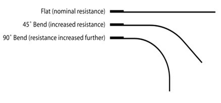
Figure 2 Three Bending Conditions of Sensor
According to figure 2, if we divide it into three cases. In case one when there is no any bend in this flex sensor then resistance would be nominal. In case two when the bend in flex sensor is 450 then the resistance would be double as compared to case one. Similarly , in case three when the bend in the sensor is 900 then the resistance would be double as compared to case one and four time as compared to case 1.So,if we talk about ratio then this resistance is directly proportional to bending angle means it is increased as well as angle is increased.
How to Interface Flex Sensor with Arduino Board?
For measuring bend, bending angle of any instrument, flex sensor is used with type of controller such as microcontroller or Arduino etc. Here we shell tell the user how interface it with Arduino board. For interfacing with Arduino board this sensor is powered up with Arduino board. When it is connected with Arduino board then its pin one is connected to +5V Arduino board pin through 100K ohm resistor and pin two is directly connected to Arduino ground pin. Similarly, a wire is connected between the center point of 100K ohm resistor and flex sensor to Arduino board A0 pin. For check proposes, a led is connected to the PWM on Arduino board shown in figure 3
Figure 3 Interfacing of Sensor with Arduino Board
Then logic program is up load in Arduino board with the help of Arduino IDE software. Similarly, when flex senor is bend then resistance is changed and this change in resistance could be seen by changing the intensity of LED light.