Recommended Components
The following parts are used in this article, along with a generic electronics kit that is handy for building and testing the circuit.
| Component | How it’s used | Buy on Amazon |
|---|---|---|
| HEF4013 / CD4013 dual D flip-flop | The HEF4013 (CD4013) dual D-type flip-flop IC this article covers. | Check Price |
| Electronic component assortment kit (1390 pcs) | A handy assortment of resistors, capacitors, LEDs, diodes and transistors for building circuits. | Check Price |
| Digital multimeter (AstroAI) | Measures voltage, current, resistance and checks continuity while you build and debug. | Check Price |
| Breadboard | Solderless base for prototyping the circuit. | Check Price |
| Jumper Wires | Make the connections on the breadboard. | Check Price |
As an Amazon Associate we earn from qualifying purchases. Prices and availability are accurate as of the date/time indicated and are subject to change.
HEF4013 Pinout
According to the pinout diagram, this dual D flip-flop IC consists of 14 pins. Out of these 14 pins, six pins are assigned for each D type FF. However, power supply pins are the same for both.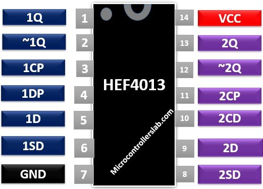
Pin#01, 13: 1Q, 2Q
Output pins that provide true outputs of the flip flops.Pin#02, 12: ~1Q, ~2Q
These two pins provide complemented outputs.Pin#03, 11: 1CP, 2CP
The clock pulse pin provides a clock pulse as an input which sends the data on the output pins on positive edge transition.Pin#04, 10: 1CD, 2CD
The clear-direct asynchronous inputs reset the two flip flops when applied with HIGH logic level.Pin#05, 09: 1D, 2D
These pins act as a data input pin.Pin#06, 08: 1SD, 2SD
It is an active HIGH, asynchronous set-direct input.Pin#07: Vss
Connect this pin to ground or 0 V.Pin#14: VDD
Connect this pin to a voltage supply.HEF4013 Features
- Asynchronous set-reset inputs
- Operating voltage = 2V to 15V.
- Output current == 0.640mA.
- Static Flip-Flop operation.
- It operates at medium speed. For 10V supply, the clock toggle rate is 16 MHz.
- Schmitt-triggered clock input’s which makes the circuit highly tolerant of slower clock rise and fall times.
- The operation of the chip is specified from -40 °C to +125 °
Where to use it?
Due to the latching ability of flip flops, the HEF5013 IC deploys in time delay circuits. These devices are designed for use in shift register applications and for performing data and memory hold functions. You can use this IC in designing counters or performing toggle operations by connecting the output pin to the data input of flip flop.How to use HEF4013?
HEF4013 is a simple dual flip flop IC that operates just like other flipflops. It changes output according to the data input, clear set input, and the clear direct input on every positive transition of a clock signal. In case of high to low transition of a clock, the outputs will not change. These two flip flops store the data input values at outputs until they are changed. The table given below indicates the effect of changing inputs on outputs.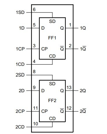
Truth Table FF
This table is for both flip flops. Set and reset functions are independent of the clock.
Proteus Simulation
Supply 5V to pin 14 and ground pin 7. Apply clock signal at pin 3 and pin 11 which can be obtained from 555 timer IC or frequency generator. The data input pin, clear data and set direct pin are connected to pull-down resistors as shown in the circuit below. You can connect LEDs to the outputs to observe their values. If the clear data and set data inputs are low, then the output value will not change, and it will retain the previous values. If both clear set pin and the set direct pin are high, only in that case both outputs will be high.
Control LED with a push button Example Circuit
The IC has complemented outputs in all cases except when both the CD and SD pins are HIGH. Therefore, it can function as a toggle by connecting LED at outputs. When one LED is on, the other will be in off state. HEF4013 is used in computers and memory devices for storing bits.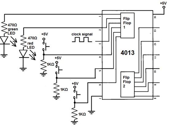
Equivalents and Alternatives
74LS76, CD4013, CD40147, CD4027Applications
Some applications of the HEF4013 are:- Computers, data terminals, and registers
- Counters/dividers
- Automotive
- Alarm system
- Toggle flip-flops
- Instrumentation
- Industrial and medical electronics
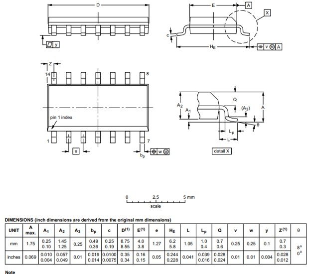
2D Diagram