In this tutorial, we will learn to use a simple transformer in proteus.
Recommended Lab Equipment & Components
Recommended lab equipment and components for building and testing the circuits you design in Proteus on real hardware. This is a general-purpose electronics bench setup plus reference books.
| Item | How it’s used | Buy on Amazon |
|---|---|---|
| Electronic component assortment kit (1390 pcs) | General kit of resistors, capacitors, LEDs, diodes and transistors for building circuits. | Check Price |
| Digital storage oscilloscope (Siglent SDS1102CML+, 100 MHz) | Two-channel bench oscilloscope for viewing and debugging real waveforms. | Check Price |
| Adjustable DC bench power supply (0-30V / 0-10A) | Regulated variable power supply for powering and current-limiting your circuits. | Check Price |
| DDS function / signal generator (dual-channel) | Generates sine, square and arbitrary waveforms for testing circuit response. | Check Price |
| Digital multimeter (AstroAI) | Measures voltage, current, resistance and checks continuity while you build and debug. | Check Price |
| Soldering iron kit (60W, adjustable temperature) | For assembling and repairing circuits on perfboard or PCB. | Check Price |
| Breadboard | Solderless base for prototyping the circuit. | Check Price |
| Jumper Wires | Make the connections on the breadboard. | Check Price |
| Arduino Uno R3 | Popular microcontroller board for the microcontroller-based examples. | Check Price |
| Book: Practical Electronics for Inventors (4th Ed.) | Hands-on reference covering components, circuits and design techniques. | Check Price |
| Book: The Art of Electronics (3rd Ed.) | The classic authoritative reference on analog and digital circuit design. | Check Price |
| Book: Make: Electronics (Learning by Discovery) | Beginner-friendly, project-based introduction to electronics. | Check Price |
As an Amazon Associate we earn from qualifying purchases. Prices and availability are accurate as of the date/time indicated and are subject to change.
- First, open your proteus software.
- After that go to components explorer by clicking on icon P from the left sidebar.
- Now type transformer in the components search bar.
- In the components window, you can see different types of transformers, but we will use only a simple iron core transformer in this proteus tutorial,
- Now double click on the simple transformer, it will be placed in selected components window, as you can see here,
- After that, place the transformer in the simulation window by simply clicking and moving your cursor towards the simulation window.
- Now double click on the transformer to open its properties window.
- In the properties window, you can see a lot of options, such as transformer primary and secondary inductance, coupling factor, primary and secondary resistance.
- These parameters are used to set the transformer to step up or step down the voltage range.
- But before changing these values, let’s see the transformer turns ratio calculation formula,
- This is the formula,
Vout = Vin / (Lp/Ls)Here V in and V out is input and output voltages respectively. In other words, V in is a primary side voltage, and V out is a secondary sid voltage of a transformer.
Here LP by Ls is the coupling ratio between the primary and secondary coils, and Lp and Ls are the inductances of the primary and secondary coils respectively. This rate is also called the coupling coefficient.
For a ratio of 10 to 1, this transformer works as a step-down transformer, having a coupling ratio of 10. But for this, we are Assuming an idea lossless transformer,
Let’s say we want to convert 220 volts AC into 22 volts AC. With these values, the coupling factor will be 10. Now, lets put coupling factor value in the transformer setting.
After that connect an AC voltage source with a transformer. Now connect 220 volts source to the primary side of the transformer, and also connect an AC voltmeter to the secondary side.
Double click on AC voltage source and set frequency to 50 hertz, and voltage to 311 volts which is the peak voltage of 220 volts RMS.
Now click on the simulation play button, as you can see the output voltage is 22 volts, which is reduced by a factor of 10.
Now let’s see primary and secondary side voltages waveforms, using analog graphs. For that, we need to connect the voltage probe’s primary and secondary side of the transformer. From sidebar select Probe mode, connect output voltage probes to both sides of the transformer.
- Now add an analog graph to check waveforms of the output voltage.
- After that attach voltage probes to the analog graph.
- In order to check output voltage waveform, right-click on the graph, and make starting and end time settings.
- Set a low time limit, because higher time will take, higher time for the simulation to complete.
- After that simulate the graph.
As you can see from the graph, the output voltage is less than the input voltage.
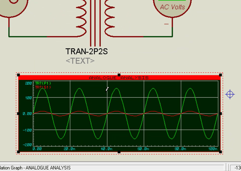
This is how we can use a transformer in proteus.
Graph font size very small. How can i increase font size?