ICL7107 is a monolithic IC used for analog to digital conversions up to 31/2 digits. It houses display drive circuitry inside it bypassing the need of connecting an external drive circuit. The input impedance is quite high. Polarity and digital drivers, segment decoders, voltage reference, and a clock circuit is already available on its board. ICL7107 is designed to connect LED display directly to it. The ADC uses a dual-slope conversion technique which inherently rejects interference signals from the ambiance. Rollover error is minimized less than one count which makes ICL7107 highly accurate.
Pinout Diagram ICL7107
This analog to digital converter display driver IC is available in different 40 pin packages. The pinout diagram depicts all the pins and their functionality. It is pretty straightforward to use this IC with seven segment displays. We can connect 4 7-segment displays starting from pin 2-20.

ICL7107 Pin Configuration Description
As we see in the last section, this ICL7107 has the following 40 pins. We will list the description of all pins one by one in this section. First, we will discuss the output pins. we connect seven segment displays wih these pins. Analog channels convert the analog voltage into a digital value. we can display these values using these output pins.
Output pins
- Pin A1 – F1 connects with the first 7-segment and it displays 1’s or unit values of digits.
- From pin A2 – F2 with second 7-segment and it displays 10’s or tens values of digits.
- Connect pin A3 – F3 with third display and it displays 100’s or hundreds of values of digits.
- Connect AB4 and POL with the last seven segment displays to display 1000’s values.
This table lists the details of other pins including an oscillator, analog channels, and other configuration pins.
Pins details table
| PINS | Details |
|---|---|
| 1 (Supply Voltage- V+) | This pin is for connecting the supply voltage |
| 2 (D1) | These pins are meant for displaying 1’s of the output value at LED display. This forms the fourth digit of LED display. |
| 3 (C1) | |
| 4 (B1) | |
| 5 (A1) | |
| 6 (F1) | |
| 7 (G1) | |
| 8 (E1) | |
| 9 (D2) | These pins are meant for displaying 10’s of the output value at LED display. This forms the third digit of LED display. |
| 10 (C2) | |
| 11 (B2) | |
| 12 (A2) | |
| 13 (F2) | |
| 14 (E2) | |
| 25 (G2) | |
| 15 (D3) | These pins are meant for displaying 100’s of the output value at LED display. This forms the second digit of LED display. |
| 16 (B3) | |
| 17 (F3) | |
| 18 (E3) | |
| 22 (G3) | |
| 23 (A3) | |
| 24 (C3) | |
| 19 (AB4) | These pins are meant for displaying 1000’s of the output value at LED display. This forms the first digit of LED display. |
| 20 (POL) | |
| 21 (BP/GND) | This pin is for connecting ground. |
| 26 (V-) | This pin is for connecting negative supply voltage. |
| 27 (INT) | This pin is for connecting a capacitor or signal integrator. |
| 28 (BUFF) | These pins are for connecting capacitors and resistive networks for auto zero & buff. |
| 29 (A-Z) | |
| 30 (IN LO) | These pins are for connecting the input which to be examined. |
| 31 (IN HI) | |
| 32 (COMMON) | This pin is normally connected to ground. |
| 33 (CREF- ) | These pins are connected to capacitor in order to filter out fluctuations. |
| 34 (CREF+ ) | |
| 35 (REF LO) | These pins are used for providing the reference voltage if required. |
| 36 (REF HI) | |
| 37 (TEST) | This pin is normally kept unused. |
| 38 (OSC 1) | These pins are used to connect components required for attaining and adjusting the frequency of oscillator. |
| 39 (OSC 2) | |
| 40 (OSC 3) |
ICL7107 Adc Display Driver Features
ICL 1707 guarantees zero reading for the input of zero volts on all scales. The typical input current is as low as 1pA. The total power consumption is less than 10mW. The operational features of ICL7107 are shown as:
| Parameters | ICL7107 |
|---|---|
| Zero input reading (Digital Reading) | +000.0 |
| Stability-last digit (Digital Reading) | +000.0 |
| Ratiometric reading (Digital Reading) | 1000 |
| Rollover error (counts) | ±1 |
| Linearity (counts) | ±1 |
| Common mode rejection ratio (µV/V) | 50 |
| Noise (µV) | 15 |
| Input leakage current (pA) | 10 |
| Zero reading drift (µV/°C) | 1 |
| Scale factor temperature coefficient (ppm/°C) | 5 |
| End power supply character V+ supply current (mA) | 1.8 |
| End power supply character V- supply current (mA) | 1.8 |
| COMMON pin analogue common voltage (V) | 3.2 |
| Temperature coefficient of analogue common (ppm/°C) | 80 |
| Display driver segment sinking current-except pin AB4 & POL (mA) | 8 |
| Display driver segment sinking current-only pin AB4 (mA) | 16 |
| Display driver segment sinking current-only pin POL (mA) | 7 |
Other display driver guides:
Where to Use ICL7107?
We can use this IC7107 display driver ic to measure analog voltage. It can measure voltage from -15 to +15 volts with a resolution of 3 ½ bit. Having a resolution of 3 ½ bit means, it can display digital values from 0000-1999. The voltage measurement range of the ADC display driver is less than or equal to a supply voltage that is ±15 volts.
We do not require any microcontroller if you are using it. Because it has a built-in 2 analog channels and display driver. Although it has many applications, mainly we can use it to design analog voltmeter, ammeter and temperature measurement meter. If you do not have embedded programming experience and you want to use displays in your project. This should be your first choice due to its ease of use.
How to use ICL7107 ADC display driver
How to set frequency?
ICL7107 has got pin no 38, 39 and 40 for connecting a resistive capacitive network for setting the oscillator’s frequency. This frequency is given by f=0.45/ RC. But the values of the resistive capacitive network should be according to these limits:
- COSC > 50pF
- ROSC > 50kΩ
- FOSC (Typ) = 48kHz
The maximum operating frequency is 48KHz. For example, if you want to operate display driver on 48KHz, select these values of resistor and capacitor:
- COSC = 100pF
- ROSC = 100KΩ
How to set reference voltage?
After making these clock adjustments a reference voltage is provided for A-D conversion. The value of the measured voltage is displayed at the LED segment display. The display count can be calculated by using
display count = 1000 x Vref/Vin
Pin35 and Pin36 are responsible for setting reference voltage. For example, if we set the reference voltage to 5 volts and Vin is 5 volts. We will see a count of 1000 on seven-segment displays. The circuit below shows the use of ICL7107 for displaying the voltage output up to 200mV.
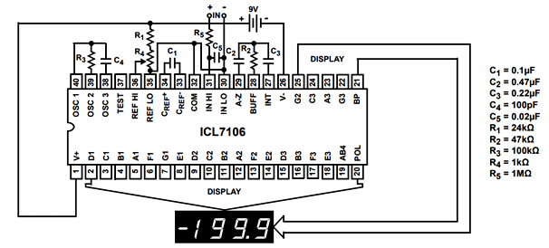
ICL7107 Example Circuits
In this section, we add example circuits using ICL7107 such as voltmeter, ammeter, and temperature sensor using this display driver. This circuit diagram shows a voltmeter that can measure the voltage between 0-5 volts.
- Voltage testing probe use as a analog voltage signal.
- This Proteus simulation diagram clearly depicts that the input voltage is 25 volts.
- The output shown on 3 seven segment displays are nearly 25 volts ~ 25.9 volts.
- Although this ic can measure a maximum of 15 volts directly, we use voltage divider circuit to lower the input voltage.

Proteus Simulation
Applications
The applications of ICL 1707 are:
- Instrument panel display
- Digital meters
- Applications based upon non-programming modules.
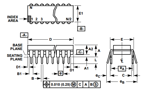
2D Dimension diagram
It is available in 40-pin DIP and MQFP packages. This picture shows a 2D model of the PDIP package.