IoT based temperature data logger using esp8266 and pic microcontroller: Hi everyone I hope you are learning about embedded systems and working on embedded systems based projects. Internet of things is a very popular topic nowadays among engineering students and professionals. Many Engineering students work on IoT based projects. In today’s project based on pic microcontroller, you will learn how to make IOT based temperature data logger using pic microcontroller and esp8266 wifi module. ThingSpeak will be used as a live monitoring server of data. You will learn how to send data to a server like thingspeak.com. In this project, we will measure temperature with LM35 temperature sensor using pic microcontroller and we will interface esp8266 wifi module with pic microcontroller. The wifi module is used to send data to server thingspeak. We will plot temperature in the form of a graph on thingspeak.
IoT based Temperature Data Logger Overview
In this project, we will monitor temperature values using an LM32 temperature sensor and plot values on a graph with ThingSpeak. We will display the temperature sensor data over the internet using the ThingSpeak server. We can access this data from anywhere in the world. So let’s first start with how to make an account with ThingSpeak.
Create ThingSpeak Account
First of all go to this website: https://thingspeak.com/users/sign_up and signup for the ThingSpeak account. After you signup just login to your account and create your channel. When you login yo your account, you will see this window:


Now click on New channel. When login to your ThingSpeak server account first time, you will need see any thing like temperature and LM35 as these are the channels created by me. So you will create your first channel by clicking on new channel. When you click on new channel, you will find this window as shown below:

Now you need to fill the information in this forum. For example we are creating this channel for IOT based temperature data logger, so we will write “temperature” in name option and you can give any description to your project. In field you will select how many graphs you want to plot. So in our case we are using temperature sensor only so will select only one label and give it a name temperature. There is also one option “Make pubic”. You can click this option also if you want to make your sever available to public. Now click on save your channel will be created.
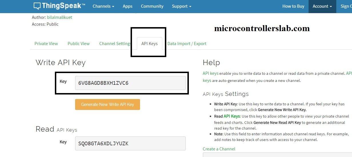
Now we need to get API keys which we will be using in our code to send and receive data from thingSpeak server. But in this project we are only sending data to server using pic microcontroller and esp8266 wifi module, so we will need only write API key. Now click on API keys options as shown below and copy write API key we will use it later in our program to upload data to server.

Now click on Data Import / Export option and you will need to copy the URL Update Channel Feed – GET. we will use this URL to upload data to ThingSpeak server. In my case URL is GET https://api.thingspeak.com/update?api_key=6VG8AGD8BXH1ZVC6&field1=0 but in your care it could be different. In this URL you need to post temperature value at the end of field1. For example if you are more than one sensor, you should get more than one fields like field1 and field2.

Further I will explain in video lecture how we will use this URL to upload temperature value to ThingSpeak. So lets check the circuit diagram and working of IOT based temperature data logger using esp8266 and pic microcontroller. I have upload temperature values of server check the diagram below:
IoT based temperature data logger circuit diagram
Circuit diagram of IOT based temperature data logger is given below:
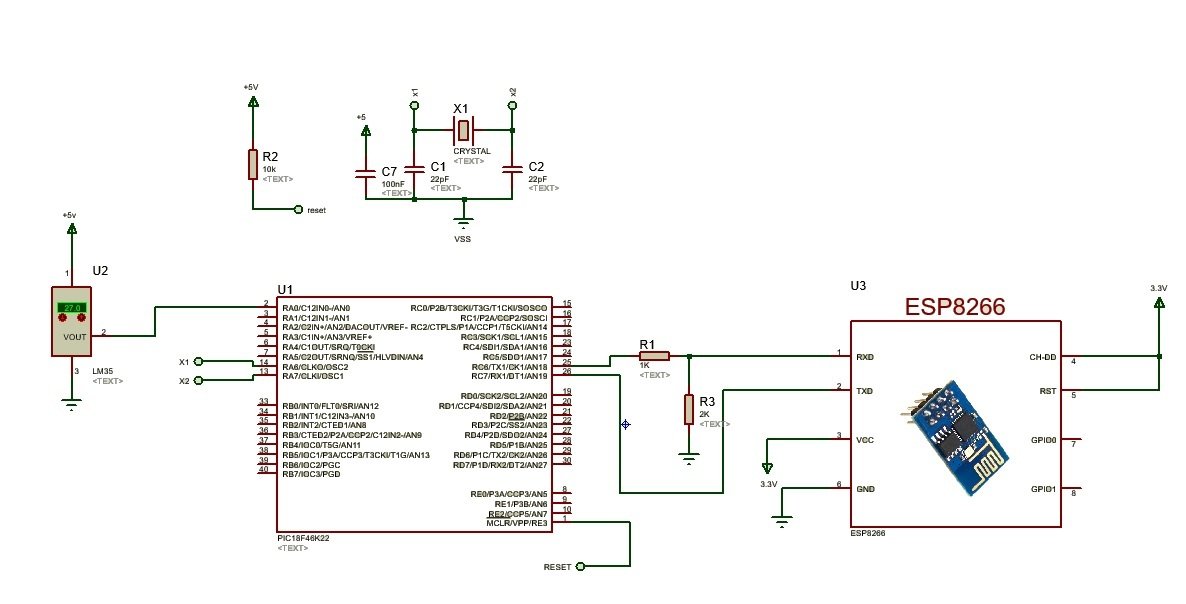
In above circuit diagram of IOT based temperature data logger using esp8266 and pic microcontroller, we are using PIC18F46K22 microcontroller. PIC18F46K22 measures temperature from LM35 temperature sensor using analog to digital converter. PIC1846K22 has built in 29 channels of analog to digital converters. Its mean we can connect 28 sensors with this pic microcontroller. But we are using only one sensor, so we will use only one channel of PIC18F46K22. LM35 temperature sensor is connect with analog channel zero of PIC16F46K22 microcontroller. Esp8266 wifi module communicate with microcontroller through serial communication and AT commands. you will send AT commands from pic microcontroller to wifi module and esp8266 wifi module will respond to these AT commands accordingly. I will explain these AT commands in later part of this article. you should know how to use serial communication of PIC18F46K22 to send AT commands to WI-FI module. Interfacing circuit is used between PIC18F46K22 and WI-FI module due in difference in operating voltages of both. Operating voltage of PIC18F46K22 is 5 volt and operating voltage of ESP8266 module is 3.3V. WI-FI module will receive data from microcontroller with AT commands and send this data to ThingSpeak server using import URL which I specified earlier.
Video lecture on IOT based temperature data logger
Code explanation for IOT based temperature data logger
sbit LCD_RS at RB0_bit;
sbit LCD_EN at RB1_bit;
sbit LCD_D4 at RB2_bit;
sbit LCD_D5 at RB3_bit;
sbit LCD_D6 at RB4_bit;
sbit LCD_D7 at RB5_bit;

sbit LCD_RS_Direction at TRISB0_bit;
sbit LCD_EN_Direction at TRISB1_bit;
sbit LCD_D4_Direction at TRISB2_bit;
sbit LCD_D5_Direction at TRISB3_bit;
sbit LCD_D6_Direction at TRISB4_bit;
sbit LCD_D7_Direction at TRISB5_bit;


unsigned char value[50],pos;
unsigned char sec;

void interrupt ()
{
if(PIR1.RCIF==1&&pos<28)
{
value[pos]=RCREG;
pos++;
PIR1.RCIF=0;


}
}
void clearVAL()
{ char i;
for(i=0;i<30;i++)
value[i]=' ';
}

void main()
{

char i,x,flag;
unsigned int adc_val;
ANSELB=0X00;
ANSELC=0X00;
ANSELA=0XFF;
TRISB=0x00;
delay_ms(2000);
INTCON.GIE=1;
INTCON.RCIE=1;
INTCON.PEIE=1;
UART1_Init(9600); // Initialize UART module at 9600 bps
adc_init();
lcd_init();
lcd_out(1,3, "ESP Temp Logger");
delay_ms(2000);
clearVAL(); //AT
lcd_out(2,2,"AT");
UART1_WRITE_TEXT("AT\r\n");
delay_ms(2000);
while(1)
{
x=strstr(&value,"OK");
if(x-32<0)
{
Lcd_Cmd(_LCD_CLEAR); // Clear display
lcd_out(2,1,"ERROR1");
break;
}
else
{
Lcd_Cmd(_LCD_CLEAR); // Clear display
lcd_out(2,1, "OK1 "); break;
}
}
delay_ms(2000);


clearVAL(); //ATE0
Lcd_Cmd(_LCD_CLEAR);
lcd_out(2,1,"ATE0");
UART1_WRITE_TEXT("ATE0\r\n");
Lcd_Cmd(_LCD_CLEAR);
while(1)
{
x=strstr(&value,"OK");
if(x-32<0)
{
Lcd_Cmd(_LCD_CLEAR); // Clear display
lcd_out(2,1,"ERROR2");
break;
}
else
{
Lcd_Cmd(_LCD_CLEAR); // Clear display
lcd_out(2,1, "OK1 "); break;
}
}
delay_ms(2000);
Lcd_Cmd(_LCD_CLEAR);


clearVAL(); //AT+CWMODE=3
lcd_out(2,1,"AT+CWMODE=3");
UART1_WRITE_TEXT("AT+CWMODE=3\r\n");
delay_ms(2000);
while(1)
{
x=strstr(&value,"OK");
if(x-32<0)
{
Lcd_Cmd(_LCD_CLEAR); // Clear display
lcd_out(2,1,"ERROR3");
break;
}
else
{
Lcd_Cmd(_LCD_CLEAR); // Clear display
lcd_out(2,1, "OK1 "); break;
}
}
delay_ms(2000);
Lcd_Cmd(_LCD_CLEAR);


clearVAL(); //AT+CIPMUX=1
lcd_out(2,1,"AT+CIPMUX=1");
UART1_WRITE_TEXT("AT+CIPMUX=1\r\n") ;
delay_ms(2000);
while(1)
{
x=strstr(&value,"OK");
if(x-32<0)
{
Lcd_Cmd(_LCD_CLEAR); // Clear display
lcd_out(2,1,"ERROR4");
break;
}
else
{
Lcd_Cmd(_LCD_CLEAR); // Clear display
lcd_out(2,1, "OK1 "); break;
}
}
delay_ms(2000);
Lcd_Cmd(_LCD_CLEAR); // Clear display
clearVAL(); //AT+CIPMUX=0
lcd_out(2,1,"connecting...");
value[0]='\0';
strcat(value,"AT+CWJAP=\"Enter your WiFi name here\",\"Enter your WiFi password here\"");
UART1_WRITE_TEXT(&value) ;
UART1_WRITE(0X0D);
UART1_WRITE(0X0A);
delay_ms(2000);
while(1)
{
x=strstr(&value,"OK");
if(x-32<0)
{
Lcd_Cmd(_LCD_CLEAR); // Clear display
lcd_out(2,1,"ERROR5");
break;
}
else
{
Lcd_Cmd(_LCD_CLEAR); // Clear display
lcd_out(2,1, "OK1 "); break;
}
}
delay_ms(2000);
sec=0;

while(1)
{
char text[8];
adc_val=adc_read(0)*4.88;
Lcd_Cmd(_LCD_CLEAR); // Clear display
inttostr(adc_val, text);
lcd_out(1,2, text);

delay_ms(2000);
lcd_out(2,1,"Uploading...");
clearVAL();
value[0]='\0';
strcat(value,"AT+CIPSTART=4,\"TCP\",\"184.106.153.149\",80");
UART1_WRITE_TEXT(&value) ;
UART1_WRITE(0X0D);
UART1_WRITE(0X0A);
sec=0;
delay_ms(2000);
while(1)
{
x=strstr(&value,"OK");
if(x-32<0)
{ lcd_out(2,1,"Error6"); flag=0; break;}
else
{ lcd_out(2,1,"OK6 ");flag=1; break; }
}
delay_ms(1000);


if(flag==1)
{
clearVAL();
value[0]='\0';
strcat(value,"AT+CIPSEND=4,46");
UART1_WRITE_TEXT(&value) ;
UART1_WRITE(0X0D);
UART1_WRITE(0X0A);
delay_ms(2000);


while(1)
{
x=strstr(&value,">");
if(x-32<0)
{ lcd_out(2,1,"ERROR7"); flag=0; break;}
else
{ lcd_out(2,1,"OK7 ");flag=1; break; }
}
delay_ms(2000);
delay_ms(2000);
if(flag==1)
{
clearVAL();
value[0]='\0';
lcd_out(2,1,"GET DATA");
strcat(value,"GET /update?key=8W4TM1V37CI3MZI5&field1="); //UPDATE CHANNEL using API
UART1_WRITE_TEXT(&value) ;
UART1_WRITE((adc_val/1000)+48);
UART1_WRITE(((adc_val%1000)/100)+48);
UART1_WRITE(((adc_val%100)/10)+48);
UART1_WRITE((adc_val%10)+48);
UART1_WRITE(0x0d);
UART1_WRITE(0x0a);
delay_ms(40000);
delay_ms(10000);
delay_ms(2000);
lcd_out(2,1,"CIPLCOSE");
clearVAL(); //AT+CIPMUX=0
value[0]='\0';
delay_ms(3000);
strcat(value,"AT+CIPCLOSE");
UART1_WRITE_TEXT(&value) ;
UART1_WRITE(0X0D);
UART1_WRITE(0X0A);
delay_ms(1000);

}
}
delay_ms(1000);

}


}
First of all ADC module of pic microcontroller is initialize to read value of temperature sensor. LM35 temperature sensor gives output in the form of voltage. This voltage is measured and converted back into voltage using following commands:
adc_val=adc_read(0)   // It will read digital value of voltage
adc_val=adc_val x 0.488  // It will convert the digital value into temperature
Following AT commands are you to configure ESP8266 module and used to send data to ThingSpeak server.
- “AT” is used to check the response of the module
- “ATE0\r\n” It is used to stop Echo back from the WI-FI module
- AT+CWMODE=3 : it is used to configure the WI-FI module both as a station and client
- AT+CWQAP : It is used to disconnect the WI-FI module from the current network
- AT+CWJAP=\”PTCL-BB\”,\”F4C0A9AB\”” : This command will connect with WI-FI module with internet connect name “PTCL-BB” and password “F4C0A9AB” . you should use your own WI-FI name and password.
- “AT+CIPSTART=4,\”TCP\”,\”184.106.153.149\”,80″: This command is used to set the port connection and address of port. Where 84.106.153.149 is IP address of ThingSpeak.com
- AT+CIPSEND=4,46 : This commands tells the WI-FI module how many bytes we want to send to server
- GET /update?key=8W4TM1V37CI3MZI5&field1=value : This command will send the value to server.
You may also like to read:
- HTTP GET using ESP32 and Arduino IDE (OpenWeatherMap.org and ThingSpeak)
- ESP32 HTTP POST using Arduino IDE (ThingSpeak and IFTTT)
- MicroPython: Send Sensor Readings via Email (IFTTT) with ESP32 and ESP8266
- MicroPython: OpenWeatherMap API with ESP32/ESP8266
- ESP8266 Wi-Fi module interfacing with Arduino: send data to server
please mail me the code for iot based temperature data logger to ushalakshmi1729@gmail.com
hello, this is a very nice project, please could you please send the code for the micro my mail is angel.ampueda@gmail.com
Good night friend, I would like to know if it is possible to send two data to thingspeak with the pic. I am trying to send to two fields of a channel but I can not
hi,
Is it possible to send continous ADC values from pic microcontroller to matlab and from matlab send to thingspeak ??
yes it is possible. For that first you need to send data by COM pin to microcontroller and then you can use MATLAB script to send data to thingsspeak
Thanks for ur reply, hey can u help me out in matlab scripting to send data to Thingspeak.
I have a similar application but its not working.
The measurement and display part is work but the communication is the problem.
On proteus simulation virtual terminal I can see the pic sending AT+Commands to the esp8266 wifi module and this is what I’m expecting .
On hardware after downloading the hex, I don’t get any data on thingspeak. The blue led on the esp8266 module flash and this tells me that something is happening, may theres communication, but I don’t know.
Please assist and advice.
dear sir
i made baud rate of pic and esp8266 – 9600 as per your coding pic transmit at commands esp8266 recieving flash blue led
but it’s not updating the data Thingspeak cloud i don’t why I think lot of people facing same problem
humble request kindly reply me sir
Very good project, I would like to try it, can anyone please send me the code.
abejjaji@gmail.com
I liked this project very much. Can you tell me that wether we need to connect the esp through usb port?
Plz send me the microcontroller code for the project.
hi, can you send me the code for this project?
how we shall connect proteus diagram to thingSpeak?
How can you sent multiple sensor data to the cloud? Your help will be appreciated
It is helpful to start something other on the IOT based embedded system projects, but The detail function definition for the methods like UART_init, UART_WRITE_TEXT are not mentioned there. or is there something hidden from me?
thank you.
Hi,
these functions are the part of built-in UART library in MikroC for PIC compiler.
I have emailed you. Please reply as soon as possible. I need to purchase the code immediately.
hello, this is very useful project , can you send me this project code?
I have a similar application but its not working.
The measurement and display part is work but the communication is the problem.
On proteus simulation virtual terminal I can see the pic sending AT+Commands to the esp8266 wifi module and this is what I’m expecting .
On hardware after downloading the hex, I don’t get any data on thingspeak. The blue led on the esp8266 module flash and this tells me that something is happening, may theres communication, but I don’t know.
Please assist and advice.
i changed baud rate 9600 esp8266
communication is the problem after downloading hardware its not working
same George issue
kindly send me code sabaritechnical@gmail.com