In this tutorial, we will learn to interface KY-023 Joystick module with Arduino. First, we will see some introduction, pinout, and working of the module, After that, we will take a sample Arduino sketch for joystick module to read its state such as x-axis, y-axis, etc. In other words, we will read 2-axis motion. Additionally, we will see how to use Processing IDE for controlling animation using joystick 2-axis motion.
Recommended Components
The following components are used in this project or are helpful for building it with the Arduino.
| Component | How it’s used in this project | Buy on Amazon |
|---|---|---|
| Arduino Uno R3 | Reads the joystick’s two analog axes and button to track position and clicks. | Check Price |
| Breadboard | Holds the joystick module and routes its connections to the Arduino. | Check Price |
| Jumper Wires | Connect the joystick VRx, VRy, SW and power pins to the Arduino. | Check Price |
As an Amazon Associate we earn from qualifying purchases. Prices and availability are accurate as of the date/time indicated and are subject to change.
KY-023 Joystick module
The Joystick module is a very simple self-centered spring-loaded module similar to S2 (PlayStation 2). It consists of two variable resistors and a push button. Variable resistors provide output in the form of analog voltage and push-button provides output in digital form either low state or high state. One Potentiometer is for x-axis control and another Potentiometer is for Y-axis control.
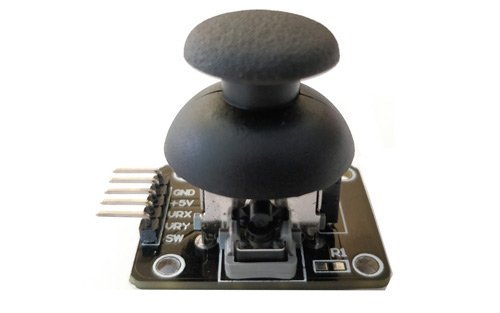
An important thing to note here is that the Joystick features two 10k potentiometers one for each axis that provides variable voltage. The KY-023 joystick module aims to provide two-dimensional (x-axis and y-axis) motion to a microcontroller.
There is a push-button at the center which is used to control the z-axis dimension. It is turned on when you press the black cap down.
PinOut
The joystick module consists of 5 pins. The description of each pin is given below:
| Pin Number | Pin Name | Description |
|---|---|---|
| 1 | GND | Connect to ground terminal of Arduino |
| 2 | +5v | Connect 5-volt pin of Arduino |
| 3 | VRx | It provides voltage w.r.t x-axis position of the joystick. (left/right) |
| 4 | VRy | It provides voltage w.r.t Y-axis position of the joystick. (up/down) |
| 5 | SW | Switch at the center. This pin gives the output obtained from the push button. When the push button is released the output will be HIGH and when it will be pressed the output will be LOW. |
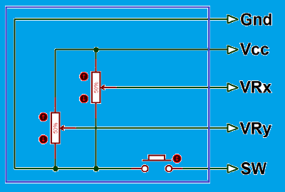
The internal circuit diagram of the joystick module is shown below:
Joystick Module Working
The Joystick Module works on the basic principle of two potentiometers and a Gimbal Mechanism. These two mechanisms make it easier to determine the position of the Joystick (right, left, up, and down) using the Arduino board.
Each potentiometer is connected to each of the Joystick’s shafts. They are used to determine the position of the rod. The position is interpreted as analog values from the Arduino board.
The resistance of the potentiometer changes as the joystick’s physical position is varied. This change is measured through the ADC pins of the Arduino board. Analog pins in the Arduino board are marked with the letter ‘A’ e.g. A0, A1, A2, A3, A4. They have 5 built-in analogs to digital converter channels. Only these analog pins of Arduino can be used to measure analog signals.
When we move joystick module on the left or the right side value of VRX varies. When we move this module up or down, the value of VRY varies. When we move it in diagonal direction values of both VRX and VRY vary. When we press it in the middle position, the SW pin becomes high. The values of VRX, VRY, and SW changes according to the picture shown below.
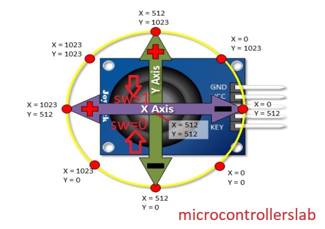
You may notice in the diagram above that the value varies between 0-1023. This is because in Arduino UNO each analog channel is a 10-bit ADC. Therefore the values are between 0-1023.
Interfacing Joystick Module with Arduino
Following components are required:
- Arduino
- Joystick Module
- Connecting Wires
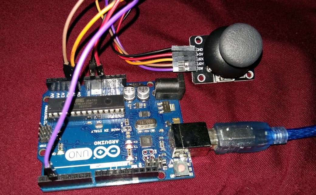
Follow the schematic diagram below:
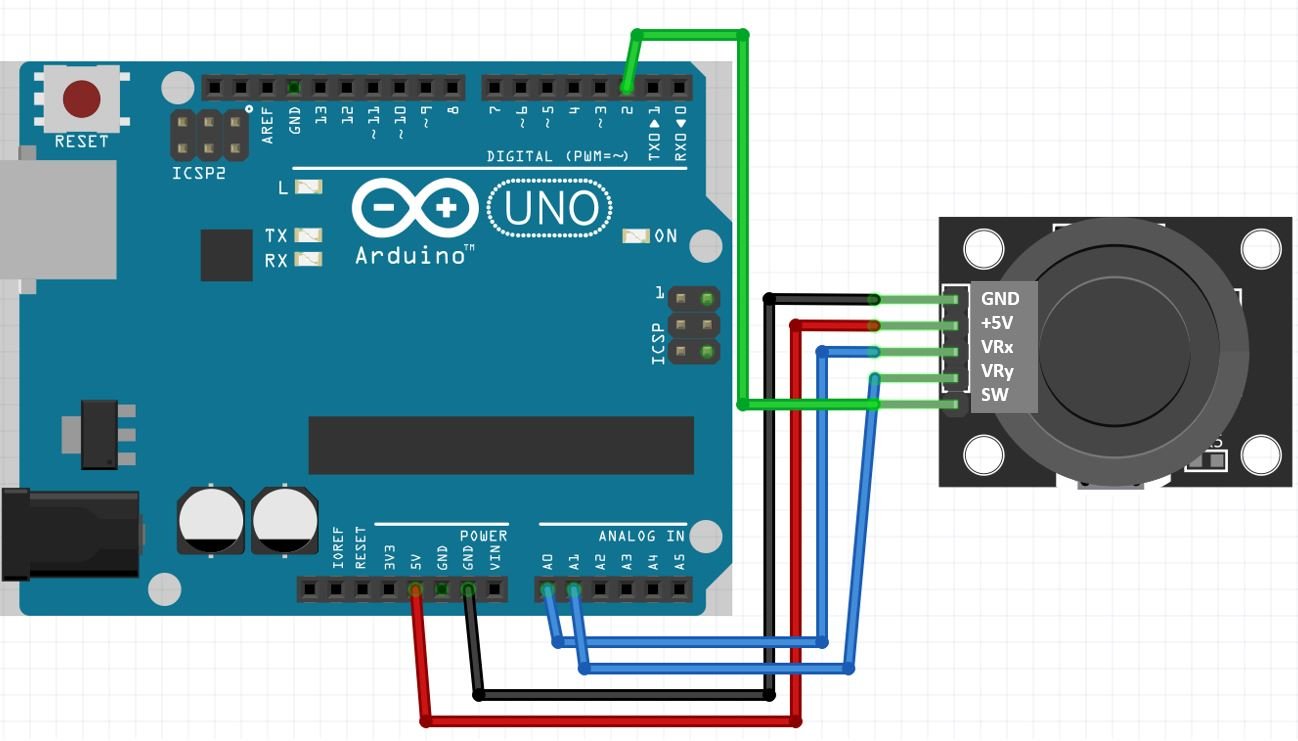
As you may see, the Joystick module has 5 pins which we will connect with the Arduino board. Connect +5V pin of joystick module with 5V Arduino pin. Then connect both the GND pins together. We have used analog pins A0 and A1 of the Arduino board to connect with VRx and VRy pins of the joystick module respectively. Additionally, we have connected digital pin 2 of Arduino with the SW pin of the module. You can use any appropriate analog pin of Arduino to connect with VRx and VRy pins and any appropriate digital pin of Arduino to connect with SW.
Arduino Sketch: Reading analog/digital input from Joystick Module
Open your Arduino IDE and go to File > New to open a new file. Copy the code given below in that file.
This sketch will display on the serial monitor, the Joystick physical positions in terms of x and y coordinates. Moreover, the switch output will be shown as well.
const int SW = 2;
const int VRx = 0;
const int VRy = 1;

void setup() {
  Serial.begin(115200);
  pinMode(SW, INPUT);
  digitalWrite(SW, HIGH);
}

void loop() {
  Serial.print("Switch:  ");
  Serial.println(digitalRead(SW));
 if (!digitalRead(SW))
  {
    Serial.println("Push button pressed!");
  }
  Serial.print("X-axis: ");
  Serial.println(analogRead(VRx));
  Serial.print("Y-axis: ");
  Serial.println(analogRead(VRy));
  Serial.println();
  delay(3000);
}
How the Code Works?
We will first define the analog and digital pins that we have connected with the VRx, VRy, and SW pins of the Joystick module.
const int SW = 2;
const int VRx = 0;
const int VRy = 1;
Inside the setup() function we will first open the serial communication at a baud rate of 115200. Next, we will configure the SW pin as an input using the pinMode() function. Then we will set the SW pin to HIGH initially. The SW pin is HIGH when the push button is not pressed.
void setup() {
  Serial.begin(115200);
  pinMode(SW, INPUT);
  digitalWrite(SW, HIGH);
}
Inside the loop() function, we will first read the switch output. This will be achieved using the digitalRead() function and passing the pin as a parameter inside it. This function will return ‘1’ if the SW output is HIGH and ‘0’ if the SW output is LOW. Note that a HIGH output means push button is not pressed and a LOW output means the push button is pressed.
Serial.print("Switch:  ");
Serial.println(digitalRead(SW));
The following lines of depicting will print “Push button pressed!” whenever the switch output is low.
if (!digitalRead(SW))
  {
    Serial.println("Push button pressed!");
  }
Next, by using analogRead() and first passing VRx pin and then VRy pin we will acquire the x and y-axis positions of the joystick.
All these three readings SW, VRx and VRy will be displayed in the serial monitor after every 3 seconds.
  Serial.print("X-axis: ");
  Serial.println(analogRead(VRx));
  Serial.print("Y-axis: ");
  Serial.println(analogRead(VRy));
  Serial.println();
  delay(3000);
Demonstration
Choose the correct board and COM port before uploading your code to the board.
Go to Tools > Board and select Arduino.

Next, go to Tools > Port and select the appropriate port through which your board is connected. Click on the upload button to upload the code into the Arduino development board. After you have uploaded your code to the Arduino press its RST button.
Now open the serial monitor and set the baud rate to 115200. Move the joystick in different directions and you will be able to view the corresponding x-axis and y-axis positions along with the switch output. Now press the push button. The switch output will now be ‘0’ and you will receive a message displaying that the push button was pressed.
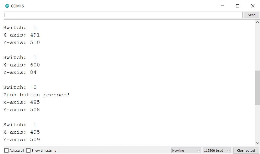
Notice how the x-axis and y-axis values vary as you move the joystick. This will be helpful to understand the different physical positions of the joystick.
Processing IDE Animations of Joystick
Now as we have seen how to monitor the different physical positions of the joystick using the Arduino sketch above let us move ahead and animate it as well. We will use Processing IDE to show animations controlled via the Joystick module.
You can install Processing IDE from the following link: https://processing.org/download
First, we will use Arduino IDE to program our Arduino board to send VRx, VRy, and SW values to the serial port. These values will then be obtained in the Processing IDE and used to animate the various positions of the Joystick.
Arduino Sketch: Processing
Open your Arduino IDE and go to File > New to open a new file. Copy the code given below in that file.
This sketch will send the x-axis and y-axis positions of the Joystick along with the switch state to the serial port.
const int SW = 2;
const int VRx = 0;
const int VRy = 1;

int xAxis = 0 ;
int yAxis = 0 ;
int Switch = 0 ;

void setup()
{
  Serial.begin(9600) ;
  pinMode(SW,INPUT) ;
  digitalWrite(SW,HIGH);
}

void loop()
{
  xAxis = analogRead(VRx);
  yAxis = analogRead(VRy);
  Switch = digitalRead(SW);

  Serial.print(xAxis,DEC);
  Serial.print(",");
  Serial.print(yAxis,DEC);
  Serial.print(",");
  Serial.print(!Switch);

  Serial.print("\n");

  delay(10);
}
You will notice that most of the code is the same as the previous Arduino sketch. However, one thing is of value. We are separating the three values using a comma. This is necessary to separate the values while sending them for processing.
  Serial.print(xAxis,DEC);
  Serial.print(",");
  Serial.print(yAxis,DEC);
  Serial.print(",");
  Serial.print(!Switch);
Demonstration
Choose the correct board and COM port before uploading your code to the board.
Go to Tools > Board and select Arduino.
Next, go to Tools > Port and select the appropriate port through which your board is connected. Click on the upload button to upload the code into the Arduino development board. After you have uploaded your code to the Arduino press its RST button.
Processing IDE Sketch
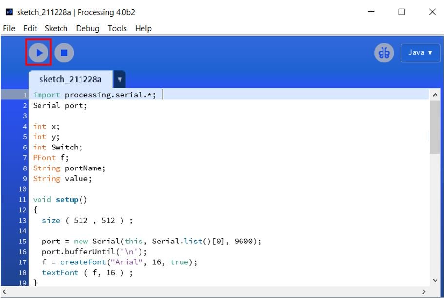
Now head over to Processing IDE and replicate the sketch given below. This will obtain the Arduino serial port data and animate the Joystick movements.
import processing.serial.*;
Serial port;

int x;
int y;
int Switch;
PFont f;
String portName;
String value;

void setup()
{
  size ( 512 , 512 ) ;

  port = new Serial(this, Serial.list()[0], 9600);
  port.bufferUntil('\n');
  f = createFont("Arial", 16, true);
  textFont ( f, 16 ) ;
}

void draw()
{
  fill(0) ;
  clear() ;
  fill(255) ;

  if (Switch == 1) // if the button is pressed
  {
    // draw a larger circle
    ellipse(x/2,y/2,100, 100);
  }
  else
  {
    // draw a smaller circle
    ellipse(x/2,y/2, 25, 25);
  }

  text("AnalogX="+(1023-x)+" AnalogY="+(1023-y),10,20);
}

void serialEvent( Serial port)
{
  // read the data until the newline n appears
  value = port.readStringUntil('\n');

  if (value != null)
  {
        value = trim(value);

    // break up the decimal and new line reading
    int[] values = int(splitTokens(value, ","));

    x = values[0];
    y = values[1] ;
    Switch = values[2];

  }
}
How the Code Works?
The first step is to include the serial library and then create an object of it called ‘port.’
import processing.serial.*;
Serial port;
Inside the setup() function we will open the serial port and also specify the different parameters for the animation.
void setup()
{
  size ( 512 , 512 ) ;

  port = new Serial(this, Serial.list()[0], 9600);
  port.bufferUntil('\n');
  f = createFont("Arial", 16, true);
  textFont ( f, 16 ) ;
}
Inside the draw function, we will set up the circle that will be shown on the screen to show the joystick position. A larger circle will be shown if the push button is pressed otherwise the regular sized one will be shown instead. Additionally, the x-axis and y-axis values will also be shown on the animation screen.
void draw()
{
  fill(0) ;
  clear() ;
  fill(255) ;

  if (Switch == 1) // if the button is pressed
  {
    // draw a larger circle
    ellipse(x/2,y/2,100, 100);
  }
  else
  {
    // draw a smaller circle
    ellipse(x/2,y/2, 25, 25);
  }

  text("AnalogX="+(1023-x)+" AnalogY="+(1023-y),10,20);
}
The serialEvent() function is responsible to read the serial port data. Remember we had separated our values with commas in the Arduino sketch. The comma will be used here to separate the three values VRx, VRy, and switch and save them in their respective variables that were initially defined.
void serialEvent( Serial port)
{
  // read the data until the newline n appears
  value = port.readStringUntil('\n');

  if (value != null)
  {
        value = trim(value);

    int[] values = int(splitTokens(value, ","));

    x = values[0];
    y = values[1] ;
    Switch = values[2];

  }
}
Demonstration
After uploading the Arduino sketch to your board it’s time to Press the run button as shown below.
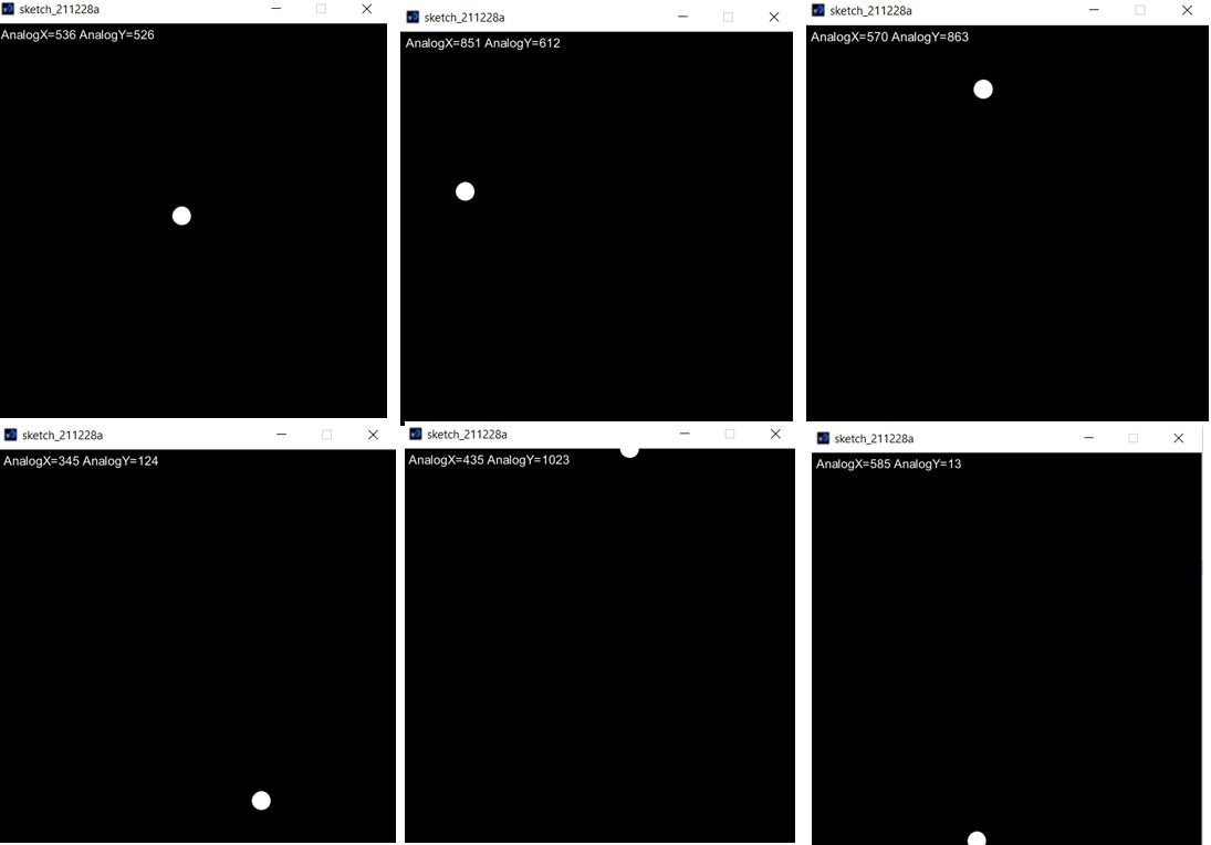
The animation window will appear. Initially, the circle is in the center as the joystick’s position is not yet moved.
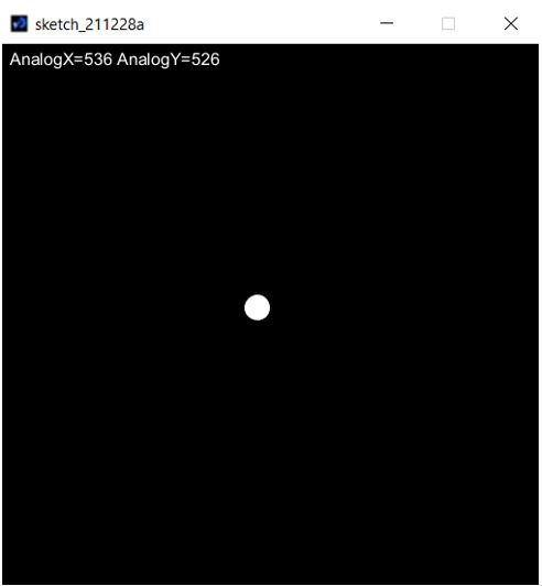
Now move the joystick around and the circle will move in a similar manner. The x-axis and y-axis positions can also be seen at the top of the window.
In conclusion, we looked at how to use the Joystick module with Arduino and how to obtain x-axis and y-axis position values. We also used Processing IDE to show you how to animate the Joystick positions using a circle. The KY-023 joystick we used was analog and it provided more accurate readings than the simple directional joysticks. However, the Joystick is not very sensitive to positional changes because Arduino ADC conversion is not that precise.
You may like to read: