This LCD interfacing with MSP430 LaunchPad tutorial shows you how to connect a 16×2 character LCD to the MSP430G2553 microcontroller and display text using the Energia IDE. LCDs are one of the most common output components in embedded systems — they let your microcontroller display sensor readings (temperature, voltage, current, weight), status messages, menu systems, counters, and error codes in a format that humans can read at a glance, without needing a PC or serial monitor attached.

Recommended Components
The following components are used in this project or are helpful for getting started with MSP430 LaunchPad development.
| Component | How it’s used in this project | Buy on Amazon |
|---|---|---|
| MSP430G2 LaunchPad | The MSP-EXP430G2 LaunchPad (MSP430G2553) used in this project. | Check Price |
| Mini-USB Cable | Type-A to Mini-B cable to program and power the LaunchPad over USB. | Check Price |
| 16×2 LCD | HD44780 character LCD that displays the text and counter output. | Check Price |
| 10kΩ Potentiometer | Adjusts the LCD contrast for readable characters. | Check Price |
| Breadboard | Solderless board for wiring the LCD and potentiometer circuit. | Check Price |
| Jumper Wires | Connect the LaunchPad header pins to the LCD data and control lines. | Check Price |
As an Amazon Associate we earn from qualifying purchases. Prices and availability are accurate as of the date/time indicated and are subject to change.
If you are learning microcontroller programming, knowing how to drive an LCD is a must-have skill — almost every real-world MSP430 project sooner or later needs some kind of display. Several types of LCDs exist on the market — 16×2, 16×4, 20×4, 20×2, and so on — but they all use the same HD44780 controller and the same wiring pattern, so the techniques in this tutorial transfer directly to any other HD44780-based LCD you may have.
What You Will Learn
- How a 16×2 character LCD works internally and what the HD44780 controller does for you
- The pinout of a standard 16-pin HD44780 LCD and the function of every pin
- The difference between 4-bit and 8-bit LCD interface modes and why 4-bit is almost always the right choice
- Why the R/W pin should be tied to GND for write-only operation (and the correct R/W logic)
- How to power a 5 V LCD from the MSP430G2 LaunchPad’s TP1 rail
- How to wire the LCD contrast potentiometer for readable characters
- A complete circuit diagram for LCD interfacing with the MSP430G2553
- How to use the Energia
LiquidCrystallibrary to write text and counter values to the LCD - Two complete working examples: static two-line text and a dynamic 1 Hz counter
- How to troubleshoot the most common LCD problems: blank display, black boxes, gibberish characters
Prerequisites and Required Components
- MSP430G2 LaunchPad (MSP430G2553)
- 16×2 character LCD module (HD44780 controller)
- 10 kΩ potentiometer (for contrast adjustment)
- Breadboard and jumper wires
- USB cable for the LaunchPad (the LCD will also be powered from this via the TP1 5 V rail)
- Energia IDE installed and configured — see the MSP430G2 LaunchPad getting started tutorial
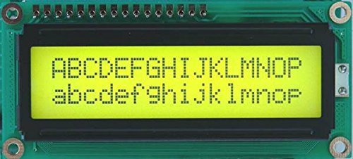
Introduction to the 16×2 Character LCD
A 16×2 LCD (also called an alphanumeric LCD) is a character display that can show up to 32 characters at a time — 16 characters per line × 2 lines. Each character cell is a small 5×8 dot matrix, so a full 16×2 display is actually 5 × 8 × 16 × 2 = 1,280 individual pixels you could in theory control. Fortunately, you never have to control them directly. Every 16×2 LCD module of this type has a built-in HD44780 (or compatible) controller that handles the dot-level rendering for you; all you do from the microcontroller side is send the controller bytes of ASCII text and a handful of control commands.
For more background on the HD44780 and 16×2 LCD internals, see:

16×2 LCD Pinout Explained
A standard 16×2 HD44780 LCD has 16 pins. Here is what each one does:
- Pin 1 – VSS: Ground (0 V)
- Pin 2 – VDD: Power supply, typically +5 V
- Pin 3 – V0 (Contrast): Contrast control. Connected to the wiper of a 10 kΩ potentiometer between +5 V and GND. Turn the pot to adjust character visibility — too high, characters are invisible; too low, the whole display shows black boxes.
- Pin 4 – RS (Register Select): Selects whether you are sending a command (RS=0) or character data (RS=1) to the controller.
- Pin 5 – R/W (Read/Write): Selects write mode (R/W=0) or read mode (R/W=1). For almost all projects we only write to the LCD, so this pin is tied to GND.
- Pin 6 – EN (Enable): Latch signal. The HD44780 samples RS and the data pins on the falling edge of EN, so every command or character transfer pulses this pin briefly.
- Pins 7–14 – D0 to D7: 8-bit parallel data bus. In 4-bit mode (used in this tutorial) only D4–D7 are connected; D0–D3 are left unconnected.
- Pin 15 – LED+ (Backlight anode): Usually +5 V through a small current-limiting resistor (often 220 Ω).
- Pin 16 – LED− (Backlight cathode): Ground.

LCD Interfacing with MSP430G2 LaunchPad
A 16×2 LCD requires a +5 V supply and draws approximately 10–20 mA (backlight off; with backlight on, closer to 80 mA). It has 16 pins total, but you do not need to wire every one — in 4-bit mode we only connect 6 control/data lines to the MSP430.
4-bit vs 8-bit LCD Interface
The HD44780 supports two interface modes:
- 8-bit mode: uses all 8 data pins (D0–D7). Sends one byte per write. Needs 8 GPIO pins on the MSP430 just for data, plus RS and EN — total 10 pins.
- 4-bit mode: uses only D4–D7. Sends one byte as two 4-bit nibbles (high nibble first). Needs only 4 data pins plus RS and EN — total 6 pins.
4-bit mode saves 4 GPIO pins at the cost of slightly slower writes (two pulses per byte instead of one). Because the MSP430G2553 only has 16 GPIO pins total, 4-bit mode is almost always the better choice — it leaves you plenty of free pins for sensors, buttons, and other peripherals. This tutorial uses 4-bit mode throughout.
R/W Pin — Always Tie to GND for Write-Only Operation
Most microcontroller LCD projects only ever write to the display — they do not need to read back the LCD’s internal state or busy flag. In that case, the cleanest solution is to tie R/W directly to GND, fix the LCD in “write” mode permanently, and free up another MSP430 GPIO pin. The R/W logic is:
- R/W = 0: Write mode — MCU sends data to the LCD controller.
- R/W = 1: Read mode — MCU reads status or data back from the controller.
For the rest of this tutorial, R/W stays at 0 (connected to GND).
LCD Circuit Diagram

The wiring in the diagram above maps to the following MSP430G2 LaunchPad header pins:
- LCD VSS (pin 1) → LaunchPad GND
- LCD VDD (pin 2) → LaunchPad TP1 (5 V)
- LCD V0 (pin 3) → wiper of 10 kΩ potentiometer (outer pins to 5 V and GND)
- LCD RS (pin 4) → LaunchPad header pin 2 (P1.0)
- LCD R/W (pin 5) → LaunchPad GND
- LCD EN (pin 6) → LaunchPad header pin 3 (P1.1)
- LCD D4 (pin 11) → LaunchPad header pin 4 (P1.2)
- LCD D5 (pin 12) → LaunchPad header pin 5 (P1.3)
- LCD D6 (pin 13) → LaunchPad header pin 6 (P1.4)
- LCD D7 (pin 14) → LaunchPad header pin 7 (P1.5)
- LCD LED+ (pin 15) → 5 V via 220 Ω resistor
- LCD LED− (pin 16) → GND
Voltage note: the MSP430 runs on 3.3 V, but the LCD wants 5 V. Power the LCD from the LaunchPad’s TP1 (raw USB 5 V rail), not the 3.3 V rail. Luckily, the HD44780 recognizes the MSP430’s 3.3 V GPIO outputs as valid logic HIGH — the input-threshold spec is around 0.7 × VDD (~3.5 V for VDD = 5 V), but in practice 3.3 V works reliably with most HD44780 modules. If you run into reliability issues, add a level-shifter IC between the MSP430 and the LCD data pins.
MSP430G2 LaunchPad LCD Code Example 1 — Static Text
The first example displays two lines of static text on the LCD: “IOT LAB” on line 1 and “MSP430 BOARD” on line 2. The code uses Energia’s built-in LiquidCrystal library, which is fully compatible with the HD44780 controller — the same API Arduino programmers use.
#include <LiquidCrystal.h>   // Energia's built-in LCD library

// LCD pin mapping (header pin numbers on the LaunchPad)
#define RS 2
#define EN 3
#define D4 4
#define D5 5
#define D6 6
#define D7 7

LiquidCrystal lcd(RS, EN, D4, D5, D6, D7);  // tell the library how the LCD is wired

void setup()           // runs once when the MSP430 resets
{
  lcd.begin(16, 2);    // 16 columns, 2 rows
}

void loop()            // runs repeatedly
{
  lcd.setCursor(0, 0);         // column 0, row 0 (top-left)
  lcd.print("IOT LAB");

  lcd.setCursor(0, 1);         // column 0, row 1 (second line)
  lcd.print("MSP430 BOARD");

  delay(1000);
}
Upload the sketch, adjust the contrast potentiometer until the characters are clearly visible, and you will see both lines of text on the 16×2 LCD.
MSP430G2 LaunchPad LCD Code Example 2 — Counter Display
The second example displays a counter that increments once per second. The static label “Counter value” stays on line 1; the numeric value updates on line 2. This is the canonical pattern for displaying any live data — sensor readings, elapsed time, step counts, and so on.
#include <LiquidCrystal.h>   // library for HD44780 LCDs

#define RS 2
#define EN 3
#define D4 4
#define D5 5
#define D6 6
#define D7 7

LiquidCrystal lcd(RS, EN, D4, D5, D6, D7);
int i = 0;

void setup()
{
  lcd.begin(16, 2);
  lcd.setCursor(0, 0);
  lcd.print("Counter value");  // static label — only print once
}

void loop()
{
  lcd.setCursor(4, 1);         // column 4, row 1 — where the number goes
  lcd.print(i);
  delay(1000);
  i++;
  lcd.setCursor(4, 1);
  lcd.print("      ");         // overwrite with spaces so old digits don't linger
}
Tip: avoid calling lcd.clear() inside a loop() that redraws the entire screen every iteration — it causes visible flicker on every update. Instead, print the static label once in setup(), then in loop() only update the specific cursor position that changes, overwriting the old digits with spaces before printing the new value. The example above uses this pattern.
Troubleshooting 16×2 LCD Issues on MSP430
- LCD backlight lights up but no characters appear. Contrast is wrong. Turn the 10 kΩ potentiometer slowly from one end to the other — at one point you will see either blocks of black rectangles (too dark) or faint text (just right). Stop there.
- LCD shows a single row of black rectangles and nothing else. The HD44780 is not being initialized — check RS and EN wiring, check D4–D7 wiring, and confirm the contrast pot is connected.
- Random garbage characters on screen. Usually one of the data pins is miswired or floating. Check D4–D7 connections carefully against the circuit diagram. Another common cause: a loose connection on EN makes the LCD latch data at the wrong time.
- Display shows the first line only, second line is blank.
lcd.begin(16, 2)was called with wrong parameters, or the LCD is a 16×1 module pretending to be 16×2. Double-check the module’s spec. - LCD works but flickers.
lcd.clear()is being called every iteration ofloop(). Removelcd.clear()and instead overwrite only the characters that change. - LCD fails to initialize after a power cycle. The HD44780 needs a brief power-on reset time (~40 ms after VDD stabilizes). Most libraries handle this, but if you’re seeing this issue, add
delay(50)at the start ofsetup()beforelcd.begin(). - Nothing works and the MSP430 appears hot. Either you accidentally wired VDD (5 V) to an MSP430 GPIO pin, or there’s a short somewhere. Disconnect power immediately and re-check wiring.
Frequently Asked Questions
Why should I use 4-bit mode instead of 8-bit mode for the LCD?
4-bit mode saves four GPIO pins with no meaningful downside. The MSP430G2553 only has 16 GPIO pins total, and 4-bit LCD mode leaves you 10 free for sensors, buttons, and communication. The only cost is that each byte is sent as two 4-bit nibbles, making writes slightly slower — but for 16×2 character LCDs the update rate is plenty fast enough for any real-world display.
Why do I see black rectangles instead of text?
Either the contrast potentiometer is too high (turn it down) or the LCD hasn’t been initialized. Every HD44780 LCD at power-on shows a row of solid rectangles in the top line — that’s a sign the panel itself is alive but the controller hasn’t received any commands yet. If the rectangles persist after your sketch runs, check RS and EN wiring.
Can I run the 16×2 LCD from 3.3 V instead of 5 V?
Some HD44780 modules work at 3.3 V (look for “VDD 3 V–5 V” on the datasheet), but the majority require 5 V. The LaunchPad’s TP1 test point provides 5 V from the USB rail, which is the cleanest solution. For a specifically 3.3 V LCD, you can wire VDD to the 3.3 V rail — but most beginner LCDs from online stores are the 5 V variety.
Can I print variables like sensor readings or floats to the LCD?
Yes. lcd.print() accepts the same types as Serial.print() — integers, floats, strings, and chars. For floats, pass a second argument to specify decimal places: lcd.print(temperature, 2) prints a float with 2 decimal places. Always overwrite the old reading with spaces before printing the new one, to avoid leftover digits when the number of characters shrinks.
How do I avoid flicker when updating the LCD frequently?
Do not call lcd.clear() on every iteration — that blanks the whole screen and causes visible flicker. Instead, print static labels once in setup(), and in loop() use lcd.setCursor() to move to only the position that changes, then overwrite that field with spaces before printing the new value. This is called the “partial redraw” pattern and is the standard technique for HD44780 LCDs.
Can I use an I2C LCD backpack with the MSP430G2 LaunchPad?
Yes. An I2C LCD backpack reduces the wiring from 6 pins to 2 (SDA and SCL). The MSP430G2553 has hardware I2C on the USCI module (pins P1.6/SCL and P1.7/SDA by default on Energia). Install the LiquidCrystal_I2C library, wire SDA/SCL and power, and the rest of the code is nearly identical to the 4-bit example above.
Conclusion
You now know how to interface a 16×2 LCD with the MSP430G2 LaunchPad in 4-bit mode using Energia IDE. You learned the HD44780 pinout, why 4-bit mode and write-only R/W wiring are the right defaults, how to build the full circuit including the contrast potentiometer, and two complete working code examples — static text and a live counter. The same technique scales directly to 20×4 LCDs, I2C backpacks, and to displaying any data your sensors produce. Next in the MSP430G2 series we move to scrolling text animations on the same LCD, and after that, UART communication.
Related MSP430G2 LaunchPad Tutorials
- Scrolling Text on LCD using MSP430 Microcontroller
- MSP430G2 LaunchPad Getting Started Tutorial with Energia IDE
- MSP430G2 LaunchPad GPIO Tutorial – Input/Output Pins
- PIR Motion Sensor Interfacing with MSP430G2 LaunchPad
- UART Serial Communication with MSP430 Microcontroller
- How to Use ADC of MSP430 Microcontroller
- Pulse Width Modulation using MSP430 LaunchPad – Control LED Brightness