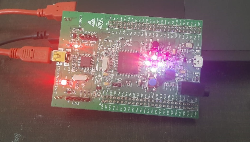
In this tutorial, we will learn to use GPIO pins of the STM32F4 discovery board. We will see an LED blinking example using the onboard LED of the STM32F4 discovery board and HAL drivers in Keil uvision IDE for ARM. In this LED blinking tutorial, we will use onboard LEDs of the latest version of the STM32F4 discovery board which is MB9970. But the same programming examples and concepts are also applicable to older versions of STM32F4DISCOVERY.
In this series of tutorials, we will use Hardware Abstraction Layer (HAL) drivers of STM32 microcontrollers. The reason for using HAL libraries is that HAL is officially supported by STMicroelectronics. On top of that code developed for one family of STM32 family can be easily ported to other STM32 families such as F0, F1, F2, F4 and F7.
STM32F4 discovery board GPIO Pins
This development board comes with a 32-bit STM32F407VGT6 microcontroller which belongs to the F4 family of ST microcontrollers and based on ARM Cortex-M4 architecture. Microcontrollers which belong to STM32F407xx support up to 140 GPIO pins with interrupt capability out of which up to 136 fast GPIOs up to 84 MHz and up to 138 5 V-tolerant GPIOs. STM32F407VGT6 microcontroller which comes with a microcontroller has 82 GPIO pins. These GPIO pins are arranged in ports such as PORTA, PORTB, PORTC, PORTD, PORTE, PORTF, PORTG, PORTH, PORTI and each port has up to 16 pins.
Note: Not all ports have up to 16GPIO pins because some pins are reserved for other functions.
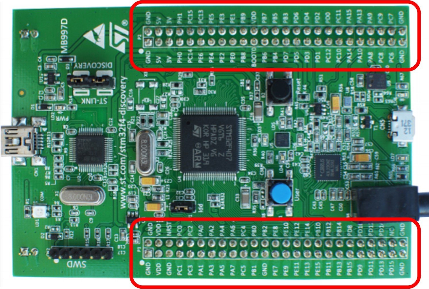
But on the STM32F4 discovery board only 5 GPIO ports are available to use on the two connector headers from PORTA, PORTB, PORTC, PORTD, PORTE and a total of 80 GPIO pins are available to use from two headers as shown in the figure below:
OnBoard LEDs STM32F4 Discovery Board
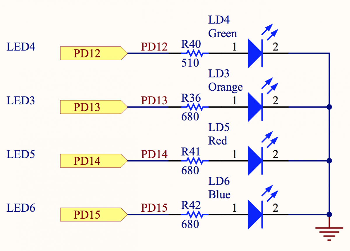
The Discovery board comes with four user LEDs connected with PD12, PD13, PD14 and PD15 pins of PORTD through a current limiting resistor.
| LED Color | LED NAME | Pin Number |
|---|---|---|
| Green | LD4 | PD12 |
| Orange | LD3 | PD13 |
| Red | LD5 | PD14 |
| Blue | LD6 | PD15 |
- LD3: orange LED is a user LED connected to the GPIO pin PD13 of the STM32F407VGT6
- LD4: green LED is a user LED connected to the I/O PD12 of the STM32F407VGT6
- LD5: red LED is a user LED connected to the I/O PD14 of the STM32F407VGT6
- LD6: blue LED is a user LED connected to the I/O PD15 of the STM32F407VGT6

In this LED blinking tutorial, we will see how to blink these LEDs using HAL drivers in Keil uvision IDE.
Writing your First Program for STM32F4 Discovery Board with Keil
In this section, we will see how to create your first program with Keil uvision IDE for the STM32F4 discovery board.
Install STM32F4 HAL Drivers and Board Support Packages in keil
First, you download and install Keil uvision IDE on your system. If you don’t know how to download and install it, you can read this article:
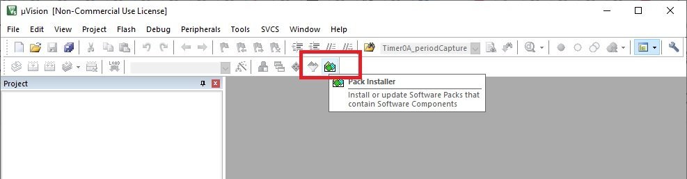
After that open Keil uvision IDE and install software packages and HAL libraries for STM32F4 in keil uvision. To install software packages, click on package installer.
After that, this package installer will appear. In this window, select STMicroelectronics->STM32F4 Series. When you double click on the STM32F4 series, their required software packages will be displayed on the right side window.
From the right window, select “Device Specific” and install drivers for STM32F4 and STM32F4 Nucleo by clicking on install buttons one by one. It will install HAL drivers and board support packages of STM32F4 family microcontrollers.

After that close this window and we are ready to create our first project of discovery board with Keil uvision IDE.
Create new project in Keil uvision
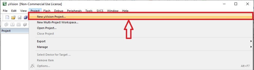
To create a new project in Keil uvision for STM32F4 discovery board, go to the Project menu and click on “New uvision project”.
The next step is to select the location where you want to save your project. Create a new folder for your project and give it a name as shown in this figure:

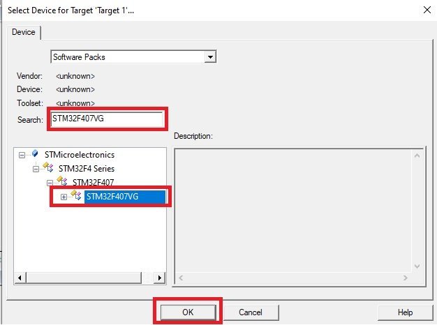
After that, “select target device” window will appear. In the search bar type “STM32F407VG” and select the microcontroller from the options and click on the “OK” button.
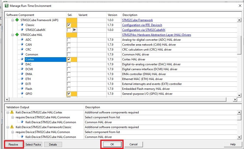
After that, the run-time environment window will appear. In this window, we need to make some mandatory and optional settings according to the peripheral of STM32F4 discovery that we want to use in our project.
- From CMSIS, check core option
- Device -> select startup
- STM32Cube Framework (API) -> select classic
- STM32Cube HAL -> select the peripheral library which you are using in your project. For example ADC, SPI, I2C, GPIO, etc.
Selecting these options may require additional software components and it will be shown in the window below. To add these additional software components, click on the resolve button. Keil uvision IDE will automatically install all required dependencies.
In this LED blinking tutorial, we will use GPIO pins of STM32F4 discovery board. Therefore, make sure to select GPIO HAL library from STM32Cube HAL.
After making all settings, click on the “OK” button, project will be created and will show like this:

Now add the main file into the STM32F4 project by right-clicking on “Source Group 1” and after that add the new c file and give it the name “main”. We will write our main LED blinking code inside this file.
STM32F4 Discovery Board LED Blinking Program
This LED blinking program toggle onboard LEDs (PD12, PD13, PD14, PD15) with a rate of 1 second. As mentioned earlier, we will use HAL drivers in this series of tutorials. Therefore, we used the GPIO HAL module driver in this LED blinking code.
#include "stm32f4xx_hal.h"

void Init_OnBoard_LEDs(void);
void Delay_ms(volatile int time_ms);
int main(void)
{
	Init_OnBoard_LEDs();
	while(1)
	{
	HAL_GPIO_TogglePin(GPIOD,GPIO_PIN_12|GPIO_PIN_13|GPIO_PIN_14|GPIO_PIN_15);
	Delay_ms(1000);
	}
}

void Init_OnBoard_LEDs(void)
{
	 __HAL_RCC_GPIOD_CLK_ENABLE();
	GPIO_InitTypeDef BoardLEDs;
	BoardLEDs.Mode = GPIO_MODE_OUTPUT_PP;
	BoardLEDs.Pin = GPIO_PIN_12|GPIO_PIN_13|GPIO_PIN_14|GPIO_PIN_15;
	HAL_GPIO_Init(GPIOD, &BoardLEDs);
}
void Delay_ms(volatile int time_ms)
{
	      int j;
        for(j = 0; j < time_ms*4000; j++)
            {}  /* excute NOP for 1ms */
}
SMT32F4 GPIO HAL Driver
The HAL driver provides functions to control GPIO pins of the STM32F4 family of microcontrollers. The GPIO pins can be configured in one of the following modes:
- Digital Input mode
- Analog modeD
- Digital Output mode
- Alternate function mode
- External interrupt/event lines
“stm32f4xx_hal.h” header file contains function prototypes of all the peripherals of STM32F4 microcontrollers.
GPIO_InitTypeDef C structure is used to initilize and set mode of GPIO pins.
typedef struct
{
  uint32_t Pin;       /*!< Specifies the GPIO pins to be configured.
                           This parameter can be any value of @ref GPIO_pins_define */

  uint32_t Mode;      /*!< Specifies the operating mode for the selected pins.
                           This parameter can be a value of @ref GPIO_mode_define */

  uint32_t Pull;      /*!< Specifies the Pull-up or Pull-Down activation for the selected pins.
                           This parameter can be a value of @ref GPIO_pull_define */

  uint32_t Speed;     /*!< Specifies the speed for the selected pins.
                           This parameter can be a value of @ref GPIO_speed_define */

  uint32_t Alternate;  /*!< Peripheral to be connected to the selected pins.
                            This parameter can be a value of @ref GPIO_Alternate_function_selection */
}GPIO_InitTypeDef;
Another important C struct is a GPIO_TypeDef. The members of the GPIO_TypeDef C struct are the configuration and control registers of GPIO ports.
typedef struct
{
  __IO uint32_t MODER;    /*!< GPIO port mode register,               Address offset: 0x00      */
  __IO uint32_t OTYPER;   /*!< GPIO port output type register,        Address offset: 0x04      */
  __IO uint32_t OSPEEDR;  /*!< GPIO port output speed register,       Address offset: 0x08      */
  __IO uint32_t PUPDR;    /*!< GPIO port pull-up/pull-down register,  Address offset: 0x0C      */
  __IO uint32_t IDR;      /*!< GPIO port input data register,         Address offset: 0x10      */
  __IO uint32_t ODR;      /*!< GPIO port output data register,        Address offset: 0x14      */
  __IO uint32_t BSRR;     /*!< GPIO port bit set/reset register,      Address offset: 0x18      */
  __IO uint32_t LCKR;     /*!< GPIO port configuration lock register, Address offset: 0x1C      */
  __IO uint32_t AFR[2];   /*!< GPIO alternate function registers,     Address offset: 0x20-0x24 */
} GPIO_TypeDef;
Configure GPIO pins as Digital Output
HAL GPIO library provides these functions to control, initialize and de-initialize GPIO pins.
HAL_GPIO_Init() function initializes the GPIOx according to the input arguments specified to both parameters. Here the GPIOx can be (x=A, B, C…H, I) according to which GPIO port we want to use. GPIO_Init is a pointer to the struct GPIO_InitTypeDef which configuration information for the specified GPIO peripheral.
void HAL_GPIO_Init(GPIO_TypeDef *GPIOx, GPIO_InitTypeDef *GPIO_Init)
For example in the above LED blinking code, we used GPIOD to control onboard LEDs of discovery board such as PD12, PD13, PD14, and PD15. To initialize them as a digital output, first we create a struct variable “BoardLEDs” of type GPIO_InitTypeDef.
GPIO_InitTypeDef BoardLEDs;By using members of GPIO_InitTypeDef struct, we select the mode of boardLEDs as a digital output and also select GPIOD pins by using BoardLEDs.Pin member of the GPIO_InitTypeDef.
BoardLEDs.Mode = GPIO_MODE_OUTPUT_PP;
BoardLEDs.Pin = GPIO_PIN_12|GPIO_PIN_13|GPIO_PIN_14|GPIO_PIN_15;
After that we pass reference of “BoardLEDs” struct to HAL_GPIO_Init() function along with GPIO port name which is GPIOD to initialize PD12-PD15 pins of PORTD as digital output pins.
GPIO HAL Driver Toggle LED Function
HAL GPIO driver provides toggle function HAL_GPIO_TogglePin() which can be used to toggle any GPIO pin STM32F4 discovery board. For example, we want to toggle on board green, organe, red and blue LEDs of disovery board.
To use this function, specified the GPIO port and its pin number to which you want to toggle.
void HAL_GPIO_TogglePin(GPIO_TypeDef* GPIOx, uint16_t GPIO_Pin)
For example, we want to toggle pins PD12-PD15 of GPIOD. Therefore, we pass GPIOD as a first argument and pin numbers as a second argument to this function. These two lines are used inside the while(1) loop. This means these two statements will execute indefinitely. The delay of 1 second is added. Hence, the four LEDs will blink at a rate of 1 second.
HAL_GPIO_TogglePin(GPIOD,GPIO_PIN_12|GPIO_PIN_13|GPIO_PIN_14|GPIO_PIN_15);
Delay_ms(1000);
HAL GPIO Write Pin Function
This function is used to set or clear a specified pin of a GPIO port. The first input argument is a PORT name, a second input argument is a pin number of the selected PORT and the third input argument is the state of the pin which can be GPIO_PIN_RESET or GPIO_PIN_SET.
- GPIO_PIN_RESET -> clear the port pin to active low
- GPIO_PIN_SET -> set the port pin to active high
void HAL_GPIO_WritePin(GPIO_TypeDef* GPIOx, uint16_t GPIO_Pin, GPIO_PinState PinState)To blink onboard LEDs of STM32F4 discovery board with HAL_GPIO_WritePin() function, we can set the crossponding pins for one second and then reset the pins for one second.
HAL_GPIO_WritePin(GPIOD, GPIO_PIN_12|GPIO_PIN_13|GPIO_PIN_14|GPIO_PIN_15, GPIO_PIN_SET);
Delay_ms(1000);
HAL_GPIO_WritePin(GPIOD, GPIO_PIN_12|GPIO_PIN_13|GPIO_PIN_14|GPIO_PIN_15, GPIO_PIN_RESET);
Delay_ms(1000);
STM32F4 LED Blinking Code with HAL_GPIO_WritePin()
In this LED blinking code, we used HAL_GPIO_WritePin() function to toggle green, yellow, red and blue LEDs of discovery board.
#include "stm32f4xx_hal.h"

void Init_OnBoard_LEDs(void);
void Delay_ms(volatile int time_ms);
int main(void)
{
	Init_OnBoard_LEDs();
	while(1)
	{
HAL_GPIO_WritePin(GPIOD, GPIO_PIN_12|GPIO_PIN_13|GPIO_PIN_14|GPIO_PIN_15, GPIO_PIN_SET);
Delay_ms(1000);
HAL_GPIO_WritePin(GPIOD, GPIO_PIN_12|GPIO_PIN_13|GPIO_PIN_14|GPIO_PIN_15, GPIO_PIN_RESET);
Delay_ms(1000);
	}
}

void Init_OnBoard_LEDs(void)
{
	 __HAL_RCC_GPIOD_CLK_ENABLE();
	GPIO_InitTypeDef BoardLEDs;
	BoardLEDs.Mode = GPIO_MODE_OUTPUT_PP;
	BoardLEDs.Pin = GPIO_PIN_12|GPIO_PIN_13|GPIO_PIN_14|GPIO_PIN_15;
	BoardLEDs.Pull = GPIO_NOPULL;
	HAL_GPIO_Init(GPIOD, &BoardLEDs);
}
void Delay_ms(volatile int time_ms)
{
	      int j;
        for(j = 0; j < time_ms*4000; j++)
            {}  /* excute NOP for 1ms */
}
i was searching for this detailed tutorial for a long time you resolved all problems thanks
Very nice explanation by you. It has resolved many of my doubts.
Thankyou so much for such wonderful tutorial.