Recommended Components
The following parts are used in this article, along with a generic electronics kit that is handy for building and testing the circuit.
| Component | How it’s used | Buy on Amazon |
|---|---|---|
| LM317 adjustable regulator | The LM317 3-terminal adjustable voltage regulator this article covers. | Check Price |
| Electronic component assortment kit (1390 pcs) | A handy assortment of resistors, capacitors, LEDs, diodes and transistors for building circuits. | Check Price |
| Digital multimeter (AstroAI) | Measures voltage, current, resistance and checks continuity while you build and debug. | Check Price |
| Breadboard | Solderless base for prototyping the circuit. | Check Price |
| Jumper Wires | Make the connections on the breadboard. | Check Price |
As an Amazon Associate we earn from qualifying purchases. Prices and availability are accurate as of the date/time indicated and are subject to change.
LM317 Pinout Diagram
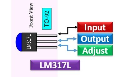
This adjustable voltage regulator is available in different pin layouts such as LM317L, LM317K, and LM317T. These diagrams show the pinout of all types. However, the functionality of all pins is the same for each type.LM317L
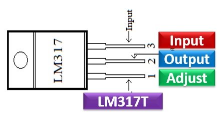
LM317T
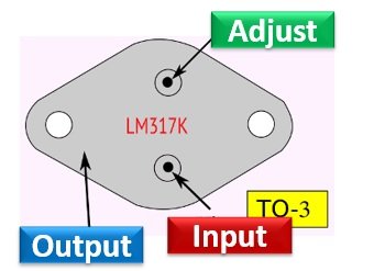
LM317K
Pin Configuration Description
It is 3 terminal device used for linear regulation of the output. The details of pins are as under:- Pin1 is an adjustable pin which is used to adjust the output voltage.
- Pin2 is an output pin and gives a regulated voltage.
- An unregulated input voltage is applied at pin 3.
LM317 Voltage Regulator Features
- An adjustable positive voltage regulator
- The output voltage can be set through an adjustable input in a range of 1.25V to 37V
- Output current is 1.5A
- Internal short-circuit protection to limit the current
- Safe area compensation for transistor output
- Operating temperature is 125°C
- Ripple rejection is 80dB
- Load regulation is typically 0.1%
- Line Regulation is typically 0.01%/V
Where to use it?
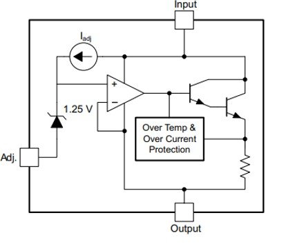
This IC is intended for use in a regulation of variable voltages. It can be used for multiple purposes. It can be used as a fixed voltage regulator, AC voltage regulator, current limiter, Battery charger, local and on-card regulation. Furthermore, it can be used as a current regulator by connecting a resistor between the output and adjustment pin. It has one drawback that during regulation its voltage drop to about 2.5V.How to use LM317 3-Terminal Adjustable Regulator?
The LM317 IC develops and maintains 1.25V between its output and adjustment pin. Its output can be adjusted by connecting a network of two resistors externally between the output pin and adjust the input pin. The two decoupling capacitors are connected in a circuit. They are used to remove the undesired coupling and avoid the effect of noise. A capacitor of 1µF is connected at the output to improve transient response. To use it is a variable regulator, we have connected a potentiometer at the adjustable pin. By changing the value of a potentiometer, you can obtain the desired voltage at the output.Simple Application circuit LM317
This is a simple example circuit using an LM317 voltage regulator. We need only two external resistors. However, we can also use capacitors to avoid voltage variations at the input and output terminals. These capacitors help to remove ripples from output voltage.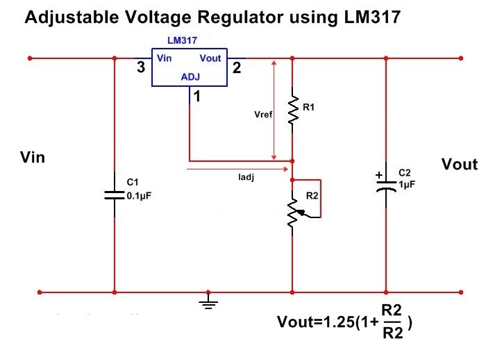 The output voltage of this circuit depends on resistor R1 and R2. The equation for calculating output voltage will be:
VOUT = 1.25 × (1 + (R2/R1))
- If R1 and R2 are minimum, the output will be equal to 1.25 volts.
- Also, if R1=R2, the output voltage will be 2.5 volts.
How to add protection Circuits?
The components can overheat due to more power dissipation. For this reason, a heat sink is used to protect the IC from overheating. The external capacitors can discharge due to the low current of the regulator. Therefore, in some applications, protection diodes are added which prevent the capacitors from discharging.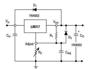 The Diode D1 protects the capacitor from discharging during an input short circuit while Diode D2 is used to protect CAdj by providing a low-impedance discharge path during an output short circuit. To achieve high ripple rejection ratios, bypass the ADJUST terminal.
Proteus Simulation Circuit Example
In this example, we use the R2 variable resistor of 10k ohm and R1=1000 ohm. The output voltage is 7.75 volts. You can also verify the results by putting resistors values in the formula given above.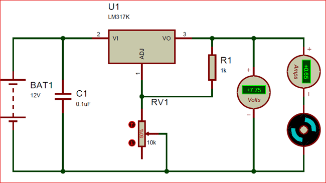 We design simulation in proteus using the library. This simulation shows the variation in output voltage according to a change in R2 resistor value.
Alternative & Equivalent Options
LT1086, LM1117, PB137, LM337- LM7805
- LM7806
- LM7809
- LM7812
- LM7905
- LM7912
- LM117V33
- XC6206P332MR.
LM317 Applications
The applications of LM317 includes:- It is a positive voltage regulator and hence used in the regulation of positive voltages.
- It is used in designing current-limiter circuits which keeps the output current in limits.

- Battery charger circuits, reverse polarity circuits, variable power supply, motor control circuits are designed using LM317 IC.
- By using two LM317 IC’s, you can regulate both the positive and negative swings of a sinusoidal AC input. Hence, AC Voltage-Regulator Circuits can be designed.
2D Diagram
It is available in three packages which are To-220, SOT223, and TO263. The dimensions of the 3 pin T0-220 package are given below.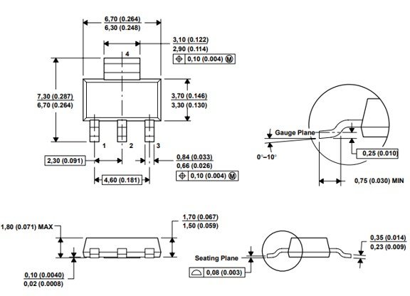
how can i buy this regulator
The equation in your diagram titled “Adjustable Voltage Regulator using LM317” is wrong – you have R2/R2. I think it’s supposed to be:
VOUT = 1.25 × (1 + (R2/R1))
show mr the proper diagram
in proteus simulation there isnt any output capacitors..will it work?
Your TO3 case as oriented = pinout is incorrect. The TO3 case (or 3) as illustrated shows output = correct. The Upper pin is incorrectly labeled. It is actually Pin 2 Input. The bottom pin is incorrectly labeled. It should show Pin 1 = Adjust, LM317k TO3 case pinouts are Pin 3 = output Pin 2 = Input Pin 1 = Adjust. The case pin offset is incorrect it seems. Thank you.