Recommended Components
The following parts are used in this article, along with a generic electronics kit that is handy for building and testing the circuit.
| Component | How it’s used | Buy on Amazon |
|---|---|---|
| Electronic component assortment kit (1390 pcs) | A handy assortment of resistors, capacitors, LEDs, diodes and transistors for building circuits. | Check Price |
| Digital multimeter (AstroAI) | Measures voltage, current, resistance and checks continuity while you build and debug. | Check Price |
| Breadboard | Solderless base for prototyping the circuit. | Check Price |
| Jumper Wires | Make the connections on the breadboard. | Check Price |
As an Amazon Associate we earn from qualifying purchases. Prices and availability are accurate as of the date/time indicated and are subject to change.
LMH1981 Pinout Diagram
This picture shows a pinout diagram of LMH1981 video synchronization separator IC.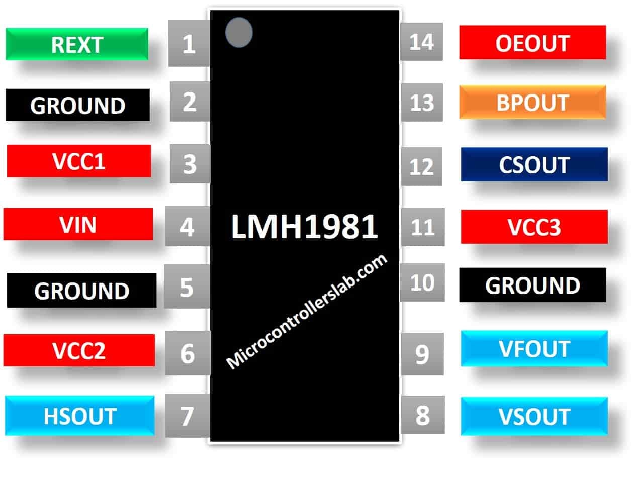
Pin Configuration
The LMH1981 IC has a total of 14 pins in which six are output pins each having different functions. All these pins along with their functionalities are mentioned in the table given below:| Pin Number | Pin Name | Description |
|---|---|---|
| 1 | REXT | An external resistor responsible for establishing the internal bias current and precise reference voltage |
| 2, 5, 10 | GND | Ground of the circuit |
| 3, 6, 11 | Vcc1, Vcc2, Vcc3 | Voltage supply |
| 4 | VIN | Video input signal |
| 7 | HSOUT | Horizontal Synchronization Output pin |
| 8 | VSOUT | Vertical Synchronization Output pin |
| 9 | VFOUT | Video Format Output detects the format of an input video signal |
| 12 | CSOUT | Composite Synchronization Output |
| 13 | BPOUT | Burst/Back Porch timing output |
| 14 | OEOUT | Odd/even field output |
LMH1981 Features
- LMH1981 can accept both Bi-level and tri-level sync video inputs
- This device has built-in ESD protection for inputs
- It has composite sync, horizontal sync, vertical sync, burst/back porch timing, odd/even field and video format outputs
- Produces a horizontal sync signal on pin 7 which has very low jitter on its leading edge.
- Automatically detect video format and applies 50% synchronization slicing for video inputs from 0.5 VPP to 2 VPP
- The voltage supply range is 3.3V to 5V and the operating supply current is 11 mA.
- It is compatible with the Macrovision system which is used in DVDs and VHS.
Where to use it?
You can use this IC in broadcast and professional video systems due to its high-performance capability and advanced features. It can automatically detect the video format therefore you don’t need to program a separate microcontroller for this purpose. It can also remove the composite video features therefore you can us this IC in all those devices which don’t support the composite synchronized information.How to use LMH1981 video Sync Separation IC?
The LMH1981 IC requires a minimum number of external components for operation. This IC is designed to separate the synchronization signals from the video signals and then output the horizontal, vertical and composite synchronization signals on the output pins 7, 8, 9 and relevant timing signals in CMOS logic. Pin 4 is connected to a video input signal from composite (CVBS), S-video (Y/C), component (YPbPr) and computer interfaces.An important feature of this IC is that it can detect the format of an input video signal automatically separates the signals that vary in amplitude by applying a 50% slicing methodology. Pin 9 which is a video format output detects the input and specifies its format on the output pin. It sends a signal in the form of the 11-bit binary data stream which specifies the vertical resolution of the input signal. This data stream is decoded by a system to determine the format. If in case the video format changes, then this pin uses to inform us about the changes in a format so that the system parameters can be adjusted.Test Circuit Example
The simple test circuit for this lmh1981 is shown in the figure below. Pin 14 is an OEOUT output signal for identifying odd and even fields for segmented frame (sF) video formats. This output is High or “1” during an odd field and low or “0” for an even field. It is constantly high for progressive video formats.
LMH1981 Applications
The video syn separator LMH1981 has applications in a wide variety of video production domains. Some of the applications are listed below:- Broadcast and Professional Video Equipment
- Composite to RGB converter modules
- HDTV/DTV Systems
- Genlock Circuits
- Video Capture Devices
- Game consoles, Set-Top Boxes (STB) & Digital Video Recorders (DVR)
- Video Displays and other entertainment systems
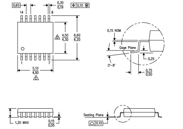
2D Diagram
This IC is available in 14 lead PDSO and SOIC packages. The two-dimensional diagram of its 14 pin PDSO package is given below: