LTC3780 DC-DC Step-up Module is a high-performance buck-boost switching regulator converter. The module is integrated with three potentiometers to regulate the voltage and current settings. Due to its constant frequency current architecture, it is capable of having a max of 400 kHz of phase-locked frequency. An FCB pin is also provided by the module to switch the modes between Buck i.e stepping down and Boost i.e. stepping up operation.
Recommended Components
The following parts are used in this article, along with a generic electronics kit that is handy for building and testing the circuit.
| Component | How it’s used | Buy on Amazon |
|---|---|---|
| LTC3780 buck-boost converter module | The LTC3780 automatic step-up/step-down DC-DC module this article covers. | Check Price |
| Electronic component assortment kit (1390 pcs) | A handy assortment of resistors, capacitors, LEDs, diodes and transistors for building circuits. | Check Price |
| Digital multimeter (AstroAI) | Measures voltage, current, resistance and checks continuity while you build and debug. | Check Price |
| Breadboard | Solderless base for prototyping the circuit. | Check Price |
| Jumper Wires | Make the connections on the breadboard. | Check Price |
As an Amazon Associate we earn from qualifying purchases. Prices and availability are accurate as of the date/time indicated and are subject to change.
LTC3780 Module Introduction
LTC3780 has a broad operating voltage input range and can power 10mA of load up to 80 Watts efficiently. An integrated fault protection circuitry is embedded in the module to prevent damage under malfunctioning. LTC3780 is suitable for either handheld electronics or industrial level power systems.
This tutorial details the pin configuration, features, specifications, interfacing, and applications.
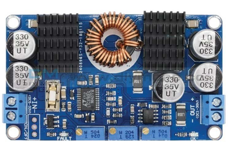
LTC3780 Components

The module consists of the following components:
Potentiometers: The module is provided with three potentiometers for Under Voltage regulation, Constant Current regulation, and Output Voltage Regulation to set the measurements according to the requirement.
Ready LED: It displays the power indication.
Input Fuse: The module is integrated with an input fuse to protect the circuitry to avoid damage. It can be replaced as well.
Fault LED: The LED will light up under faulty conditions.
LTC3780 IC: The integrated circuit does the stepping up or down of the voltage.
The following figure shows the pinot for input and output connectors to for DC power sources:

LTC3780 Pinout
The following diagram shows the pinout of the LTC3780 DC-DC Step-up module:

Pin Configuration
LTC3780 DC-DC Step-up chip has a total of 24 pins but only 4 of them are extended to the board. The pin configuration detail in tabular is mentioned below:
| Number | Pin Name | Function |
|---|---|---|
| 1 | PGOOD | Open-Drain Output pin. It should be connected to the ground if the output voltage is not within ±7.5% limit. |
| 2 | SS | Soft-Start control pin. It increases the current limitation to reduce the input power current. |
| 3 | SENSE+ | Positive Current Sense Comparator pin. It sets the current threshold. |
| 4 | SENSE– | Negative Current Sense Comparator pin. It sets the current threshold. |
| 5 | ITH | Current Control Voltage pin. It controls the threshold voltage between 0 to 2.4V. |
| 6 | V0SENSE | Error Amplifier input pin. This is used to connect error amplifier to resistor divider. |
| 7 | SGND | Signal Ground pin. Small-signal components are connected to this ground. |
| 8 | RUN | Run input Control pin. Power supply >6V to this pin will switch off the regulation circuit. |
| 9 | FCB | Forced Continuous Control Input pin. It is used to select the power mode of the module. |
| 10 | PLLFLTR | Phase locked loop filter. It is used to change the frequency of the internal oscillator. |
| 11 | PLLIN | Input Synchronization pin. It is internally connected to SGND through a 50k resistor. |
| 12 | STBYMD | LDO Control pin. It determines the working of LowDropOut when the module is off. |
| 13 | BOOST2 | Boosted Driver Supply pin. It swings diode voltage upto INTVCC+VOUT. |
| 14 | TG2 | Top Gate Drive pin. It is used to drive the n-MOSFET gate with a voltage swing equal to INTVCC. |
| 15 | SW2 | Switch node pin. It swings from Schottky voltage drop up to VIN. |
| 16 | BG2 | Bottom Gate drive pin. It is used to drive bottom n-MOSFET gate with voltage range of 0 – INTVCC |
| 17 | PGND(IN-) | Power Ground pin. |
| 18 | BG1 | Bottom Gate drive pin. It is used to drive bottom n-MOSFET gate with voltage range of 0 – INTVCC |
| 19 | INTVCC | Internal VCC pin. It powers the driver and control circuits |
| 20 | EXTVCC | External VCC pin. It should be less than VIN. |
| 21 | VIN(IN+) | Power Supply pin. |
| 22 | SW1 | Switch node pin. It swings from Schottky voltage drop to VOUT. |
| 23 | TG1 | Top Gate Drive pin. It is used to drive the n-MOSFET gate with a voltage swing equal to INTVCC. |
| 24 | BOOST1 | Boosted Driver Supply pin. It swings diode voltage upto VIN+INTVCC. |
Features and Specifications
- Operating Voltage: 4 – 36 Volts
- Synchronous Rectification Efficiency: <98%
- Output Voltage Accuracy: 0.8<VOUT<30V ±1%
- Maximum Output Current: 10A
- Phase-locked frequency Range: 200 kHz – 400 kHz
- Output Power: 80 Watts
- Peak Output Power: 130 Watts
- Package-Type: 24-Lead SSOP and 32-Lead QFN package
Useful Features
The additional features of the LTC3780 DC-DC module are listed as follows:
- The module has an integrated LDO to supply low-noise voltage for the n-MOSFET
- The module has four synchronous drive n-channel MOSFETs for functionality.
- LTC3780 has an output voltage checker to maintain the output voltage within 7.5% of the set mark.
- It is integrated with Soft-Start that shapes the current by increasing the current limit of the module.
- LTC3780 has selectable modes for operation.
- 3 selectable modes for boosting ie. Burst mode for high efficiency, discontinuous, and forced continuous mode to work at constant frequency are provided.
- 3 selectable modes for bucking ie. Skip-cycle mode for high efficiency, discontinuous, and forced continuous mode to work at constant frequency are provided.
- To protect the module from over-voltage, a fault protection circuit is embedded in it.
Alternate Options
- LM2596S DC-DC module
- XL6009 DC-DC module
LTC3780 Block Diagram
The block diagram of the LTC3780 is provided for repairing purposes. DC-DC Step-up module showing the connectivity of the IC and peripherals is as follows:

How to Connect the Input source and get output from LTC3780?
The interfacing diagram is provided below to shows connections for input and output terminals. We can connect an unregualted dc power source of 5-32V to the left two input connector. Similarly, we can get reguated DC voltage in the range of 1 – 30V from right terminal.
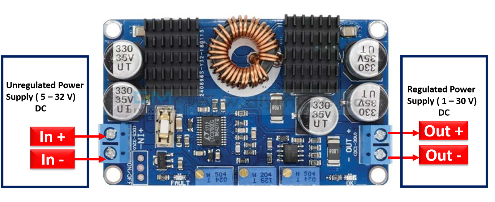
The power supply either regulated or unregulated that is required to be stepped down or boosted is connected to the Input Block of the module. The LTC3780 chip and potentiometers will adjust the DC voltage level and current as required. The load is connected to the Output Block of the module. In this way adjusted DC voltage and current is applied to drive the load circuitry. The module comes with a heat sinker but if power is more than 80Watts it is advised to use a fan along with the module.
Applications
- Communication Systems
- Automobiles
- Power Control Systems
- High power Industrial Control
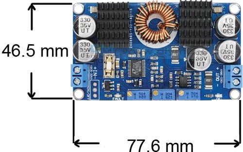
2D Diagram
Related Articles:
- DC to DC converter using push pull topology
- TC7660 Charge Pump DC-to-DC Voltage Converter
- Dc to dc buck converter simulation with Simulink
- SEPIC Converter Proteus Simulation
- Buck Converter Proteus Simulation
- Boost Converter Proteus Simulation
- Buck converter simulation using PSpice
- Single Phase to Single Phase Cycloconverter Design Using Simulink
- forward converter design and simulation with simulink