Recommended Components
The following parts are used in this article, along with a generic electronics kit that is handy for building and testing the circuit.
| Component | How it’s used | Buy on Amazon |
|---|---|---|
| MC33171 low-power op-amp | The MC33171 low-power operational amplifier this article covers. | Check Price |
| Electronic component assortment kit (1390 pcs) | A handy assortment of resistors, capacitors, LEDs, diodes and transistors for building circuits. | Check Price |
| Digital multimeter (AstroAI) | Measures voltage, current, resistance and checks continuity while you build and debug. | Check Price |
| Breadboard | Solderless base for prototyping the circuit. | Check Price |
| Jumper Wires | Make the connections on the breadboard. | Check Price |
As an Amazon Associate we earn from qualifying purchases. Prices and availability are accurate as of the date/time indicated and are subject to change.
Pin Configuration Diagram
As it is an operational amplifier, therefore it has 2 inputs and 1 output pin. The figure below shows a pinout diagram.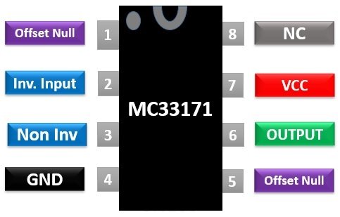 An additional input of offset Null is also provided. All the pins of this IC and their functionalities are mentioned in the table below:
| Pin Number | Pin Name | Description |
|---|---|---|
| 1, 5 | Offset Null | It is used for setting offset voltage. |
| 2 | Inv. Input | Inverting input terminal of opamp |
| 3 | Noninv. Input | Non-Inverting input terminal of opamp |
| 4 | Ground of the circuit | |
| 6 | Output | Output of opamp |
| 7 | Positive power supply | |
| 8 | NC | Not Connected |
MC33171 Low Power Operational Amplifier Features
- Low consumption of only 200µa
- Good speed of 2.1MHz in 2vµs
- Operating temperature range of -40°C to +105°C
- Pin to Pin compatible with other single operational amplifiers
- Wide input common mode range, including Ground (VEE)
- Pin to pin compatible with standard single op-amps
- Wide Bandwidth of 1.8 MHz and High Slew rate of 2.1 V/µs
- high input resistance, low input offset voltage and high gain.
- Excellent Gain Margin of 15 dB
- Output Short Circuit Protection
- ESD Diodes to protect inputs against static discharges
Equivalent Op-Amps
MC33172, MC33174, NCV33172/74Other Alternative Amplifiers
Where to use MC33171?
We can use this IC in electrical and electronics circuits. You can use this IC to perform integration operations by connecting a capacitor in the feedback loop. The output signal produced will be directly proportional to the amplitude and duration of the input signal. This IC can also be used for voltage to current conversions by applying a voltage to the non-inverting terminal and negative feedback. Some other uses of this IC are in designing of voltage follower circuits, selective inversion circuits, Active Filters, etc.How to use MC33171 Op-Amp?
This IC is very easy to use. We can use IC MC33171 as an inverting amplifier and a noninverting amplifier. In inverting mode, a voltage signal is applied at pin2 and pin 3 is grounded. The polarity of the output signal obtained in this mode is opposite to the input signal.Vout = (-Rf/R1) VinThe circuit diagram for the inverting amplifier is given below. For a non-inverting amplifier, connect the pin 3 with a voltage signal and pin 2 is grounded. Then the polarity of output obtained will be the same as the polarity of the input signal. The equation for the non-inverting amplifier is:
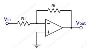
Vout = (Rf/R1) VinThe value of input voltages applied must lie between the values of supply voltages VEE and Vcc.
MC33171 Op-Amp Example Circuits
Operational amplifiers have a wide variety of applications in electrical circuits. Some of them are:Sample and Hold Circuit Example
This example circuit shows a Sample and Holds circuits using this MC33171 op-amp. We need two op-amps that connect through a switch as shown in the circuit diagram below. When the switch closes, the capacitor charges to its peak value and the sampling of the input signal performs whereas in hold form, the switch will be open and the capacitor holds the value.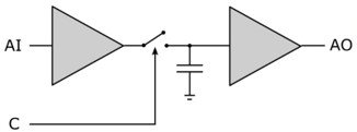
Peak Detector Circuit
In this example circuit of MC33171, we design a peak detector by connecting a capacitor and diode at its output as shown in the circuit diagram below. The diode will conduct and is forward biased when Vout is greater than Vin. On the other hand, if Vout is less than Vin diode will not conduct.
Comparator Circuit Example
It can act as a voltage comparator by applying reference voltage on pin 2 and voltage to be measured on pin 3 of the IC MC33171. If the output is positive that means voltage to be measured is greater than the reference voltage.Functional Generator Circuit
Function Generators are also designed through two operational amplifiers which can be achieved by using two IC’s of MC33171.2D-Diagram
This is a 2D diagram for 8 pin PDIP package of IC MC33171.