In this tutorial, we will see the role of startup files in microcontrollers. Firstly, what is the startup file? and what exactly is the function of the startup file in bare-metal embedded systems? In the end, we will explore the startup file of ARM Cortex M4 microcontrollers and understand important sections of this file. Now let’s get started by defining a startup file.
What is a startup file in microcontrollers?
A startup file is a piece of code written in assembly or C language that executes before the main() function of our embedded application. It performs various initialization steps by setting up the hardware of the microcontroller so that the user application can run. Therefore, a startup file always runs before the main() code of our embedded application.
The startup file performs various initializations and contains code for interrupt vector routines. As we have seen in the last tutorial when a microcontroller resets, it executes a reset handler (interrupt service routine) and performs hardware initialization before executing the main code. The startup file consists of this reset handler function and hardware initialization code.

Functions of Startup file
Following are the main functions of a startup file:
- Disable all interrupts
- Copying initialized global, global static, and local static variable data from flash to .data section RAM memory of a microcontroller
- Copying uninitialized global, global static, and local static variable data from flash to .bss section of RAM memory and initialize .bss section of RAM to zero.
- Allocate space for the stack and initialize the stack pointer
- It also contains an array of function pointers ( interrupt vector table) that point to various interrupt vector routines such as interrupts and exceptions. The startup file also contains definitions of these interrupt or exception routines such as reset handler, NMI handler, bus fault handler, etc.
- Enable interrupts
- Calls the main function
Startup.s or startup.c file is architecture-dependent, especially the vector table part.
Understand the Startup file of TM4C123G Microcontrollers
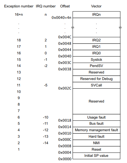
Before understanding the startup file, let’s have a quick review of the vector table. TM4C123G microcontroller starting address of flash/code memory consists of a vector table and vector table values contains the addresses of interrupt or exception handlers.
As shown in figure below, TM4C123GH6PM microcontroller has 15 exceptions and 138 IRQ interrupts. Therefore, the first 15+138 locations of code memory starting from 0x0000_0000 contain the address of exception and interrupt handlers.
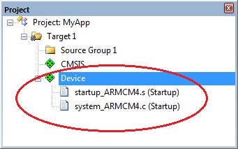
Now let’s understand the startup file of TM4C123G microcontroller. When we compile our application with Keil or any IDE, the startup file will be included automatically into our project. Keil IDE provides startup file in assembly language and code composer studio has a startup file available in c language. In this article, we will analyze the startup file of Keil compiler and it is available with the name of “startup_TM4C123.s”.
Define Stack Area
Firstly, the startup file of TM4C123G microcontroller defines the stack area section and stack size in RAM memory. In this line, EQU is a assembler directive and it works similar to #define directive of c language. This line define a constant named “Stack_Size” with the value of 0x00000200.
Stack_Size EQU 0x00000200This line provides the declaration of the stack area. In assembly, AREA is an assembler directive that is used to define a different section of memory. In this line:
- AREA: Used to define a new section
- STACK: Name of the section
- NOINT: It directs to initialize with stack memory with zero
- READWRITE: This defines that the stack memory section has both read and write permission
- ALIGN=3: Makes the starting of stack an 8-byte boundary
AREA STACK, NOINIT, READWRITE, ALIGN=3Here SPACE is assembler directive which is used to reserve space for the requested number of bytes. This line reserves 0x0400 bytes of memory to stack section.
Stack_Mem SPACE Stack_SizeNext, the __initial_sp label is used inside the vector table and it is used as a initial stack pointer.
Define Heap Area
These lines define the heap section and assign it space in memory similar to the stack memory area. Here __heap_base and __heap_limit define the starting and ending address of heap area.
Heap_Size       EQU     0x0000000
                AREA    HEAP, NOINIT, READWRITE, ALIGN=3
__heap_base
Heap_Mem        SPACE   Heap_Size
__heap_limit
These line define the ARM Cortex M4 microcontroller mode of operation which is thumb mode and Cortex M4 microcontrollers only support thumb mode.
PRESERVE8
THUMB
Interrutp Vector table Array of function Pointers
Similar to C language, this assembly code create array of pointers which hold the address of initial stack pointer and addresses of a location which contains interrupt and exception handlers addresses.
Vector Table Mapped to Address 0 at Reset
AREA RESET, DATA, READONLY
EXPORT __Vectors
EXPORT __Vectors_End
EXPORT __Vectors_Size
__Vectors DCD __initial_sp ; Top of Stack
DCD Reset_Handler ; Reset Handler
DCD NMI_Handler ; NMI Handler
DCD HardFault_Handler ; Hard Fault Handler
DCD MemManage_Handler ; MPU Fault Handler
DCD BusFault_Handler ; Bus Fault Handler
DCD UsageFault_Handler ; Usage Fault Handler
DCD 0 ; Reserved
DCD 0 ; Reserved
DCD 0 ; Reserved
DCD 0 ; Reserved
DCD SVC_Handler ; SVCall Handler
DCD DebugMon_Handler ; Debug Monitor Handler
DCD 0 ; Reserved
DCD PendSV_Handler ; PendSV Handler
DCD SysTick_Handler ; SysTick Handler
; External Interrupts
DCD GPIOA_Handler ; 0: GPIO Port A
DCD GPIOB_Handler ; 1: GPIO Port B
DCD GPIOC_Handler ; 2: GPIO Port C
DCD GPIOD_Handler ; 3: GPIO Port D
DCD GPIOE_Handler ; 4: GPIO Port E
DCD UART0_Handler ; 5: UART0 Rx and Tx
DCD UART1_Handler ; 6: UART1 Rx and Tx
DCD SSI0_Handler ; 7: SSI0 Rx and Tx
DCD I2C0_Handler ; 8: I2C0 Master and Slave
DCD PMW0_FAULT_Handler ; 9: PWM Fault
DCD PWM0_0_Handler ; 10: PWM Generator 0
DCD PWM0_1_Handler ; 11: PWM Generator 1
DCD PWM0_2_Handler ; 12: PWM Generator 2
DCD QEI0_Handler ; 13: Quadrature Encoder 0
DCD ADC0SS0_Handler ; 14: ADC Sequence 0
DCD ADC0SS1_Handler ; 15: ADC Sequence 1
DCD ADC0SS2_Handler ; 16: ADC Sequence 2
DCD ADC0SS3_Handler ; 17: ADC Sequence 3
DCD WDT0_Handler ; 18: Watchdog timer
DCD TIMER0A_Handler ; 19: Timer 0 subtimer A
DCD TIMER0B_Handler ; 20: Timer 0 subtimer B
DCD TIMER1A_Handler ; 21: Timer 1 subtimer A
DCD TIMER1B_Handler ; 22: Timer 1 subtimer B
DCD TIMER2A_Handler ; 23: Timer 2 subtimer A
DCD TIMER2B_Handler ; 24: Timer 2 subtimer B
DCD COMP0_Handler ; 25: Analog Comparator 0
DCD COMP1_Handler ; 26: Analog Comparator 1
DCD COMP2_Handler ; 27: Analog Comparator 2
DCD SYSCTL_Handler ; 28: System Control (PLL, OSC, BO)
DCD FLASH_Handler ; 29: FLASH Control
DCD GPIOF_Handler ; 30: GPIO Port F
DCD GPIOG_Handler ; 31: GPIO Port G
DCD GPIOH_Handler ; 32: GPIO Port H
DCD UART2_Handler ; 33: UART2 Rx and Tx
DCD SSI1_Handler ; 34: SSI1 Rx and Tx
DCD TIMER3A_Handler ; 35: Timer 3 subtimer A
DCD TIMER3B_Handler ; 36: Timer 3 subtimer B
DCD I2C1_Handler ; 37: I2C1 Master and Slave
DCD QEI1_Handler ; 38: Quadrature Encoder 1
DCD CAN0_Handler ; 39: CAN0
DCD CAN1_Handler ; 40: CAN1
DCD CAN2_Handler ; 41: CAN2
DCD 0 ; 42: Reserved
DCD HIB_Handler ; 43: Hibernate
DCD USB0_Handler ; 44: USB0
DCD PWM0_3_Handler ; 45: PWM Generator 3
DCD UDMA_Handler ; 46: uDMA Software Transfer
DCD UDMAERR_Handler ; 47: uDMA Error
DCD ADC1SS0_Handler ; 48: ADC1 Sequence 0
DCD ADC1SS1_Handler ; 49: ADC1 Sequence 1
DCD ADC1SS2_Handler ; 50: ADC1 Sequence 2
DCD ADC1SS3_Handler ; 51: ADC1 Sequence 3
DCD 0 ; 52: Reserved
DCD 0 ; 53: Reserved
DCD GPIOJ_Handler ; 54: GPIO Port J
DCD GPIOK_Handler ; 55: GPIO Port K
DCD GPIOL_Handler ; 56: GPIO Port L
DCD SSI2_Handler ; 57: SSI2 Rx and Tx
DCD SSI3_Handler ; 58: SSI3 Rx and Tx
DCD UART3_Handler ; 59: UART3 Rx and Tx
DCD UART4_Handler ; 60: UART4 Rx and Tx
DCD UART5_Handler ; 61: UART5 Rx and Tx
DCD UART6_Handler ; 62: UART6 Rx and Tx
DCD UART7_Handler ; 63: UART7 Rx and Tx
DCD 0 ; 64: Reserved
DCD 0 ; 65: Reserved
DCD 0 ; 66: Reserved
DCD 0 ; 67: Reserved
DCD I2C2_Handler ; 68: I2C2 Master and Slave
DCD I2C3_Handler ; 69: I2C3 Master and Slave
DCD TIMER4A_Handler ; 70: Timer 4 subtimer A
DCD TIMER4B_Handler ; 71: Timer 4 subtimer B
DCD 0 ; 72: Reserved
DCD 0 ; 73: Reserved
DCD 0 ; 74: Reserved
DCD 0 ; 75: Reserved
DCD 0 ; 76: Reserved
DCD 0 ; 77: Reserved
DCD 0 ; 78: Reserved
DCD 0 ; 79: Reserved
DCD 0 ; 80: Reserved
DCD 0 ; 81: Reserved
DCD 0 ; 82: Reserved
DCD 0 ; 83: Reserved
DCD 0 ; 84: Reserved
DCD 0 ; 85: Reserved
DCD 0 ; 86: Reserved
DCD 0 ; 87: Reserved
DCD 0 ; 88: Reserved
DCD 0 ; 89: Reserved
DCD 0 ; 90: Reserved
DCD 0 ; 91: Reserved
DCD TIMER5A_Handler ; 92: Timer 5 subtimer A
DCD TIMER5B_Handler ; 93: Timer 5 subtimer B
DCD WTIMER0A_Handler ; 94: Wide Timer 0 subtimer A
DCD WTIMER0B_Handler ; 95: Wide Timer 0 subtimer B
DCD WTIMER1A_Handler ; 96: Wide Timer 1 subtimer A
DCD WTIMER1B_Handler ; 97: Wide Timer 1 subtimer B
DCD WTIMER2A_Handler ; 98: Wide Timer 2 subtimer A
DCD WTIMER2B_Handler ; 99: Wide Timer 2 subtimer B
DCD WTIMER3A_Handler ; 100: Wide Timer 3 subtimer A
DCD WTIMER3B_Handler ; 101: Wide Timer 3 subtimer B
DCD WTIMER4A_Handler ; 102: Wide Timer 4 subtimer A
DCD WTIMER4B_Handler ; 103: Wide Timer 4 subtimer B
DCD WTIMER5A_Handler ; 104: Wide Timer 5 subtimer A
DCD WTIMER5B_Handler ; 105: Wide Timer 5 subtimer B
DCD FPU_Handler ; 106: FPU
DCD 0 ; 107: Reserved
DCD 0 ; 108: Reserved
DCD I2C4_Handler ; 109: I2C4 Master and Slave
DCD I2C5_Handler ; 110: I2C5 Master and Slave
DCD GPIOM_Handler ; 111: GPIO Port M
DCD GPION_Handler ; 112: GPIO Port N
DCD QEI2_Handler ; 113: Quadrature Encoder 2
DCD 0 ; 114: Reserved
DCD 0 ; 115: Reserved
DCD GPIOP0_Handler ; 116: GPIO Port P (Summary or P0)
DCD GPIOP1_Handler ; 117: GPIO Port P1
DCD GPIOP2_Handler ; 118: GPIO Port P2
DCD GPIOP3_Handler ; 119: GPIO Port P3
DCD GPIOP4_Handler ; 120: GPIO Port P4
DCD GPIOP5_Handler ; 121: GPIO Port P5
DCD GPIOP6_Handler ; 122: GPIO Port P6
DCD GPIOP7_Handler ; 123: GPIO Port P7
DCD GPIOQ0_Handler ; 124: GPIO Port Q (Summary or Q0)
DCD GPIOQ1_Handler ; 125: GPIO Port Q1
DCD GPIOQ2_Handler ; 126: GPIO Port Q2
DCD GPIOQ3_Handler ; 127: GPIO Port Q3
DCD GPIOQ4_Handler ; 128: GPIO Port Q4
DCD GPIOQ5_Handler ; 129: GPIO Port Q5
DCD GPIOQ6_Handler ; 130: GPIO Port Q6
DCD GPIOQ7_Handler ; 131: GPIO Port Q7
DCD GPIOR_Handler ; 132: GPIO Port R
DCD GPIOS_Handler ; 133: GPIO Port S
DCD PMW1_0_Handler ; 134: PWM 1 Generator 0
DCD PWM1_1_Handler ; 135: PWM 1 Generator 1
DCD PWM1_2_Handler ; 136: PWM 1 Generator 2
DCD PWM1_3_Handler ; 137: PWM 1 Generator 3
DCD PWM1_FAULT_Handler ; 138: PWM 1 Fault
__Vectors_EndThese lines dirtect to store this code in code/flash memory of microcontroller and __vectors location is defined inside the linker file and we will write about linker script file in coming tutorials.
__Vectors_Size  EQU     __Vectors_End - __Vectors

                AREA    |.text|, CODE, READONLY
Reset Handler Function
The startup file of microcontroller also contains rotines of interrupt and exceptions and reset handler function is one of them. This routine defines the reset handler function.
Reset_Handler   PROC
                EXPORT  Reset_Handler             [WEAK]
                IMPORT  SystemInit
                IMPORT  __main
                LDR     R0, =SystemInit
                BLX     R0
                LDR     R0, =__main
                BX      R0
                ENDP
For complete in-depth detail on how reset function of ARM Cortex microcontroller works, you can read this post:
Microcontrollers Booting Process
Other default Handlers
It also contains rountines of other exception and interrupt hanlders, but they are just a dumy routines executing while loop. But they are implemented with Weak attribute which makes it possible to redefine handler our own implementation of hanlders any where else in the project and we usually define our own handlers inside the main function.
Other related tutorials:
- Bare Metal Embedded Systems Build Process using GNU Toolchain
- Microcontroller Booting Process – Reset Sequence
- Accessing Memory Mapped Peripherals Registers of Microcontrollers
- Difference between multiprocessor and multicomputer
- Difference between Windows and Linux
- Difference between stack and heap
- Difference Between Multiprogramming and Multitasking
- Difference between preemptive and non-preemptive scheduling in Operating systems
Hello,
my comment on below point:
“Copying uninitialized global, global static, and local static variable data from flash to .bss section of RAM memory and initialize .bss section of RAM to zero. ”
:: need to copy from Flash as its value is zero so not stored on flash and in startup code after initialized data copied from flash to RAM then this uninitialized variables addresses are set to zero in RAM area and its address are already available from compiler directives. So simply use for loop from start address to end address to set value to uninitialized data.
Please correct me if wrong.
Can you upload complete startup for tm4c123 board for downloading.