This PIR motion sensor interfacing with MSP430G2 LaunchPad tutorial shows you how to connect a passive infrared (PIR) motion sensor to the MSP430G2553 microcontroller and use it to detect human movement in the environment. When motion is detected, the MSP430 turns on an LED as a visual indicator — the exact same pattern used in real-world motion-activated lights, burglar alarms, and automatic hallway lighting.
There are many types of motion sensors on the market — radar, ultrasonic, microwave — but the most common and the cheapest is the PIR (Passive Infrared) sensor, typically sold as the HC-SR501 module. In this tutorial we wire the PIR sensor’s digital output pin to a GPIO input on the MSP430G2 LaunchPad, read the pin in a simple polling loop, and drive an LED accordingly. This is a complete motion detector project you can build in 15 minutes.
Before continuing, make sure you are comfortable with the basics of GPIO input and output on the MSP430G2 LaunchPad:
- MSP430G2 LaunchPad Getting Started Tutorial with Energia IDE
- MSP430G2 LaunchPad GPIO Tutorial – Input/Output Pins
- RGB LED Interfacing with MSP430G2 LaunchPad
Recommended Components
The following components are used in this project or are helpful for getting started with MSP430 LaunchPad development.
| Component | How it’s used in this project | Buy on Amazon |
|---|---|---|
| MSP430G2 LaunchPad | The MSP-EXP430G2 LaunchPad (MSP430G2553) used in this project. | Check Price |
| Mini-USB Cable | Type-A to Mini-B cable to program and power the LaunchPad over USB. | Check Price |
| PIR Motion Sensor | HC-SR501 PIR sensor that detects human movement. | Check Price |
| 5mm LED | External LED that lights up when motion is detected. | Check Price |
| Resistor Kit (220Ω) | 220Ω current-limiting resistor for the indicator LED. | Check Price |
| Breadboard | Solderless board for wiring the PIR sensor and LED circuit. | Check Price |
| Jumper Wires | Connect the PIR sensor and LED to the LaunchPad header pins. | Check Price |
As an Amazon Associate we earn from qualifying purchases. Prices and availability are accurate as of the date/time indicated and are subject to change.
What You Will Learn
- How a PIR (Passive Infrared) motion sensor detects movement using infrared temperature changes
- The three pins on a typical HC-SR501 PIR module (VCC, GND, OUT) and what each does
- How the two onboard potentiometers (sensitivity and time delay) affect the sensor’s behavior
- Why the PIR sensor’s VCC should be powered from the LaunchPad’s TP1 (5 V) rail, not the 3.3 V rail
- How to match the sensor’s output voltage to the MSP430’s 3.3 V logic safely
- How to connect a PIR motion sensor to the MSP430G2 LaunchPad (full circuit diagram)
- How to write Energia code that reads the PIR output and turns on an LED when motion is detected
- How to configure the trigger mode (single-trigger vs repeat-trigger) on the HC-SR501
- Common PIR sensor troubleshooting: false triggers, stuck output, long warm-up time
Prerequisites and Required Components
- MSP430G2 LaunchPad (MSP430G2553)
- HC-SR501 PIR motion sensor module (or equivalent 3-pin PIR module)
- 1 × LED (any color)
- 1 × 220 Ω resistor (current-limiting for the LED)
- Breadboard and jumper wires
- USB cable for the LaunchPad (which also supplies the 5 V rail for the PIR)
- Energia IDE installed and configured
Introduction to PIR Motion Sensors

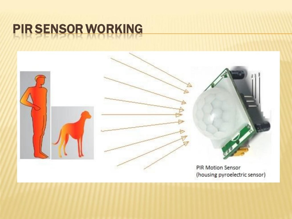
A PIR (Passive Infrared) sensor is the most common type of motion detector in consumer and hobby electronics. The “passive” in the name means it does not emit any energy of its own — it simply receives infrared radiation given off by warm objects (like humans and animals) and watches for changes in that radiation pattern over time.
Underneath the white Fresnel lens dome on the front of the module is a very sensitive pyroelectric infrared sensor that measures the background IR temperature of the room. When a warm object moves across the sensor’s field of view, it changes the IR pattern reaching the sensor element — and that change is what triggers the output. A stationary warm object does not trigger it, because there is no change in the IR pattern. This is why PIR sensors are perfect for detecting motion but terrible for detecting a person sitting still.
PIR Sensor Module Pinout
Most hobbyist PIR modules — including the ubiquitous HC-SR501 — expose just three pins:
- VCC — power supply input, typically 5 V (module accepts 4.5–20 V on most HC-SR501 variants, though the onboard LDO drops it to 3.3 V internally)
- GND — ground
- OUT — digital output pin. Idle LOW; pulses HIGH (~3.3 V) when motion is detected
The HC-SR501’s output pin is 3.3 V logic, which is directly compatible with the MSP430G2’s GPIO inputs — so no level shifter is needed. Important: if you use a PIR module from a different brand, check the output voltage with a multimeter before wiring it to the MSP430. Some cheaper modules output 5 V, which would damage the MSP430G2’s non-5-V-tolerant GPIO pins.
Onboard Adjustments: Sensitivity and Time Delay
The HC-SR501 has two small potentiometers on the PCB that let you fine-tune the sensor’s behavior:
- Sensitivity (SX): adjusts the detection range. Fully clockwise = maximum range (~7 meters / 23 ft). Fully counter-clockwise = minimum range (~3 meters / 10 ft).
- Time delay (TX): controls how long the output pin stays HIGH after motion is detected. Adjustable from ~3 seconds up to ~5 minutes. After this hold time expires, the output drops LOW and the sensor is ready to detect the next motion.
Many HC-SR501 modules also have a trigger mode jumper (labeled H / L):
- H (repeat-trigger, default): every new motion detected during the hold time extends the output HIGH period. Use this for lights that stay on while someone is still moving.
- L (single-trigger): output goes HIGH once per motion event and stays HIGH only for the programmed hold time, regardless of further motion.
A well-calibrated HC-SR501 can detect a 6-inch (15 cm) hand movement from 20 feet (6 meters) away — impressive for a component that costs a couple of dollars.
PIR Motion Sensor Interfacing with MSP430G2 LaunchPad
In this circuit we use header pin 13 (P2.5) as a digital input connected to the PIR’s OUT pin, and header pin 14 (P1.6) as a digital output driving an indicator LED. When the PIR detects motion, its OUT pin goes HIGH; the MSP430 reads this in the main loop and turns the LED on.
Powering the PIR Sensor from the LaunchPad
A quick but important note about powering the HC-SR501. The PIR module wants ~5 V on its VCC pin, but the MSP430G2 LaunchPad’s main 3.3 V regulator output (on header pin 1) is only 3.3 V. Where do you get 5 V?
The LaunchPad has a labelled test point called TP1 on the top of the board that exposes the raw 5 V USB rail coming in from your computer. TP1 is the right place to tap for 5 V when powering external modules like the HC-SR501. If you try to power the PIR from the 3.3 V rail, the onboard LDO regulator inside the HC-SR501 will not have enough headroom and the sensor will either not work at all or will behave erratically.
Power the HC-SR501 VCC from TP1 (5 V rail), but connect its OUT pin directly to the MSP430 GPIO input — the HC-SR501 output is already 3.3 V logic thanks to its internal regulator, which keeps the MSP430 safe.
PIR Sensor Circuit Diagram

Wire the circuit according to the diagram. Summary of connections:
- PIR VCC → LaunchPad TP1 (5 V)
- PIR GND → LaunchPad GND (header pin 20)
- PIR OUT → LaunchPad header pin 13 (P2.5)
- LED anode → LaunchPad header pin 14 (P1.6) via 220 Ω resistor
- LED cathode → LaunchPad GND
MSP430G2 LaunchPad Code for PIR Motion Sensor
The code is simple — functionally identical to the push button example, but we read the PIR output instead of a button. When the PIR OUT pin is HIGH, motion is detected and we turn the LED on. When OUT is LOW, we turn the LED off.
int ledpin        = 14;   // header pin 14 (P1.6) → LED
int motion_sensor = 13;   // header pin 13 (P2.5) → PIR OUT
int sensor_state;         // stores the latest PIR reading

void setup()
{
  pinMode(ledpin,        OUTPUT);
  pinMode(motion_sensor, INPUT);
}

void loop()
{
  sensor_state = digitalRead(motion_sensor);

  if (sensor_state == HIGH)           // motion detected
  {
    digitalWrite(ledpin, HIGH);       // turn LED on
    delay(1000);
  }
  else                                // no motion
  {
    digitalWrite(ledpin, LOW);        // turn LED off
  }
  delay(100);                         // small poll interval
}
How the PIR Sensor Code Works
The first three lines declare friendly names for the LED pin, the PIR pin, and a variable to hold the PIR state. Inside setup(), we configure the LED pin as an output and the PIR pin as an input. Inside loop(), we call digitalRead(motion_sensor) to sample the PIR’s OUT pin; if it reads HIGH, motion was detected within the PIR’s hold time, so we light the LED.
Because the HC-SR501 already has a built-in hold time (set by the onboard TX potentiometer), you usually do not need additional software debouncing — the sensor itself keeps the output HIGH for the configured duration (3 seconds to 5 minutes). That means you can also extend this sketch to trigger a relay, send a UART notification, or record a timestamp, without worrying about the sensor flickering HIGH/LOW rapidly.
Upload the code to the MSP430G2 LaunchPad. Wait about 30–60 seconds after power-on for the PIR to stabilize (this is the sensor’s warm-up time, during which false triggers are common). Then wave your hand in front of the lens — the LED lights up and stays on for the duration set by the TX potentiometer, then turns off.
Troubleshooting PIR Motion Sensor Issues
- LED is on all the time, even with no motion. Either the PIR is in its warm-up period (wait 30–60 seconds after power-on), or the module is set to maximum sensitivity and picking up tiny room changes. Turn the SX (sensitivity) potentiometer counter-clockwise to reduce range.
- LED never turns on. Check that VCC is connected to the 5 V TP1 rail, not the 3.3 V rail. Confirm with a multimeter. Also verify the OUT pin is actually connected to header pin 13 on the LaunchPad.
- LED stays on for too long or too short. Adjust the TX (time delay) potentiometer on the PIR. Fully counter-clockwise = ~3 seconds; fully clockwise = ~5 minutes.
- Random false triggers in a still room. PIR sensors respond to sudden IR changes — including HVAC vents blowing warm air, direct sunlight through a window, or even a fluorescent light flickering. Move the sensor or reduce its sensitivity.
- MSP430 looks damaged after connecting the sensor. You probably used a non-HC-SR501 PIR module with 5 V logic output. Always measure the OUT pin voltage before connecting it to an MSP430 input — it must be ≤ 3.6 V.
- PIR LED on the module blinks but the MSP430 LED does not. Wiring is wrong between the PIR OUT pin and header pin 13. Check the jumper wire is on the right pin of both boards.
- Sensor only triggers on the first motion after upload. The trigger mode jumper may be in “L” (single-trigger) mode. Move it to “H” (repeat-trigger) for continuous re-triggering.
Frequently Asked Questions
Can I power the HC-SR501 from the MSP430’s 3.3 V pin?
Technically some HC-SR501 variants will run at 3.3 V, but the datasheet specifies a minimum of about 4.5 V, and reliability is poor below 5 V. Always power the PIR from the LaunchPad’s TP1 (5 V USB rail) for dependable detection. The OUT pin is safe for the MSP430 regardless — it is 3.3 V thanks to the module’s onboard regulator.
How far can the HC-SR501 PIR sensor detect motion?
Typically 3–7 meters (10–23 feet), depending on the SX sensitivity potentiometer setting, the size of the moving object, and the temperature difference between the object and the background. A full human body at room temperature is easy to detect; a small animal or a person wearing heavy insulation is harder.
Why does my PIR sensor give false triggers right after power-on?
PIR sensors need a 30–60 second warm-up period after power is first applied. During warm-up the sensor is stabilizing its internal baseline IR reading, and any small change looks like motion. Either wait before trusting the output, or add a software delay at the start of your sketch: delay(30000); in setup() ignores the warm-up period cleanly.
Can I use a PIR sensor to detect stationary people?
No. PIR sensors only detect changes in infrared patterns, not the presence of heat by itself. A completely stationary person will not trigger the sensor once the PIR has adapted to their presence. For occupancy detection that works on still subjects, look at mmWave radar modules (like the LD2410) instead — they detect breathing and micro-movements.
What is the difference between H and L trigger modes on the HC-SR501?
H (repeat / retrigger): every new motion detected during the hold window restarts the hold timer, so the output stays HIGH as long as motion continues. Best for things like lights that should stay on while someone is still in the room. L (single-trigger): after motion is detected, the output stays HIGH for exactly the configured hold time, then goes LOW — even if motion is still happening. Best for counting discrete motion events.
Can I connect multiple PIR sensors to one MSP430G2 LaunchPad?
Yes. Each PIR module just needs its own GPIO input pin and shares VCC/GND with the others. The MSP430G2553 has 16 GPIO pins, so you can connect more than a dozen PIR sensors to one LaunchPad — useful for projects like multi-zone occupancy detection or hallway lighting with separate zones.
Conclusion
You have now built a complete PIR motion sensor project with the MSP430G2 LaunchPad. You learned how a passive infrared sensor works, how the HC-SR501’s three pins and two onboard potentiometers control sensitivity and hold time, why the sensor needs 5 V from the TP1 rail (and why its 3.3 V output is still MSP430-safe), and how to read motion events in a simple Energia sketch. From here you can extend the project to switch a real relay with a transistor, log timestamps over UART, or trigger a buzzer for a DIY burglar alarm.
Related MSP430G2 LaunchPad Tutorials
- MSP430G2 LaunchPad Getting Started Tutorial with Energia IDE
- MSP430G2 LaunchPad GPIO Tutorial – Input/Output Pins
- RGB LED Interfacing with MSP430G2 LaunchPad
- LCD Interfacing with MSP430 LaunchPad
- UART Serial Communication with MSP430 Microcontroller
- How to Use ADC of MSP430 Microcontroller
- Pulse Width Modulation using MSP430 LaunchPad – Control LED Brightness
Energia: 1.8.11E23 (Windows 10), Board: “MSP-EXP430G2 w/ MSP430G2553”
Sketch uses 918 bytes (5%) of program storage space. Maximum is 16384 bytes.
Global variables use 26 bytes (5%) of dynamic memory, leaving 486 bytes for local variables. Maximum is 512 bytes.
MSPDebug version 0.24 – debugging tool for MSP430 MCUs
Copyright (C) 2009-2016 Daniel Beer
This is free software; see the source for copying conditions. There is NO
warranty; not even for MERCHANTABILITY or FITNESS FOR A PARTICULAR PURPOSE.
—————– NOTE ——————
Modified version of mspdebug for Energia
Do not use standalone
—————————————–
Chip info database from MSP430.dll v3.3.1.4 Copyright (C) 2013 TI, Inc.
Using new (SLAC460L+) API
MSP430_GetNumberOfUsbIfs
MSP430_GetNameOfUsbIf
Found FET: HID0002:COM4
MSP430_Initialize: HID0002:COM4
Firmware version is 20409001
MSP430_VCC: 3000 mV
MSP430_OpenDevice
MSP430_GetFoundDevice
Device: MSP430G2xx3 (id = 0x00de)
2 breakpoints available
MSP430_EEM_Init
Chip ID data:
ver_id: 5325
ver_sub_id: 0000
revision: 00
fab: 60
self: 0000
prog: ‘C:\Users\ravib\AppData\Local\Temp\arduino_build_995363/sketch_sep11a.ino.hex’: The filename, directory name, or volume label syntax is incorrect.
config: 00
Device: MSP430G2xx3
MSP430_Run
MSP430_Close
An error occurred while uploading the sketch
can you help me to solve this problem. i’m ussing msp-exp430g2553