In this tutorial, we will learn how to program STM32 Blue Pill through USB port by uploading Bootloader to the board. It is a step by step guide which will help you to install STM32 Bootloader and then program your Blue Pill through the micro USB port using Arduino IDE.
The STM32 Blue Pill comes with a micro USB port but it does not contain the Arduino ready boot loader. Therefore, we use USB-TTL converter to upload code as the board is not discoverable if connected through the USB port. Moreover, as seen in previous STM32 Blue Pill tutorials, in order to successfully upload code we had to move the BOOT jumper from 0 to 1 to enable the microcontroller to go into programming mode. Therefore, in order to utilize the USB port of Blue Pill ad upload code just like with other microcntrollers like Arduino, ESP32 etc. we will install the bootloader. Follow this step by step guide to successfully blink the onboard LED of your Blue Pill with Arduino IDE through the micro USB port.
Prerequisites
Before we move ahead, let us list the hardware components and the software packages that will be required for this guide.
Hardware Required
- STM32F103C8 Board
- USB-TTL Converter
- Connecting Wires
- Breadboard
- 1.5k ohm resistor (if required)
Software Required
- STM32 Flash Loader (Download from this link)
- STM32duino Bootloader generic_boot20_pc13.bin (Download from this link)
- STM32 USB Mini Driver (Download from this link)
Circuit Setup to Flash Boot Loader
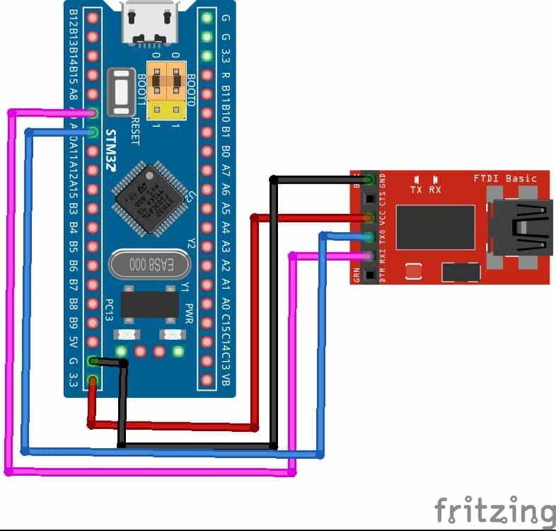
In order to successfully flash the boot loader we will have to first connect our STM32 Blue Pill with a USB-TTL converter/FTDI programmer. Follow the table below to connect the two devices.
| USB-TTL Converter | STM32 Blue Pill |
|---|---|
| VCC | 3.3V |
| GND | GND |
| RX | PA9 |
| TX | PA10 |
Upload Maple Bootloader to STM32 Blue Pill
After connecting your STM32 Blue Pill with a USB to TTL converter, let us show you the process to upload the maple boot loader to our Blue Pill.
- First connect STM32 Blue with USB to TTL converter as shown in the circuit diagram above. Make sure to move the BOOT jumper from 0 to 1 to enable the microcontroller to go into programming mode. Now plug the USB to TTL converter in your computer.

- Next, make sure you have downloaded the STM32duino Bootloader generic_boot20_pc13.bin (Download from this link) file from this link.
- Now, download the STM32 Flash Loader (Download from this link)
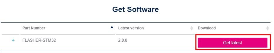
Download the STM32 flasher by first accepting the license agreement, registering your account on my.st.com and then you will get the download link on your email.
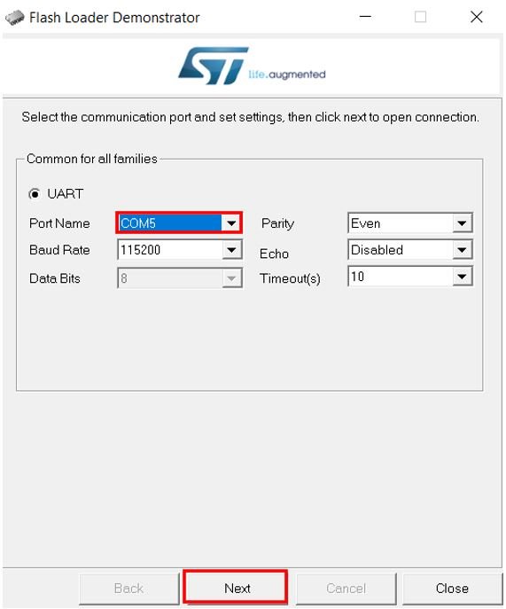
- Open the STM32 flasher. It will detect the COM port through which the USB to TTL converter is connected. You can even confirm the COM port through the Device Manger. In our case it is COM5. Click ‘Next’ to proceed further.
- As our connections are proper, hence target is readable message appears. Click ‘Next’ to proceed further.

- The target is automatically detected. Click ‘Next.’

- Now select the ‘Download to device’ option and click the box with the three dots highlighted below:

- Select the generic_boot20_pc13.bin file that we previously download from its saved location. Then, click ‘Next’ to procced further.

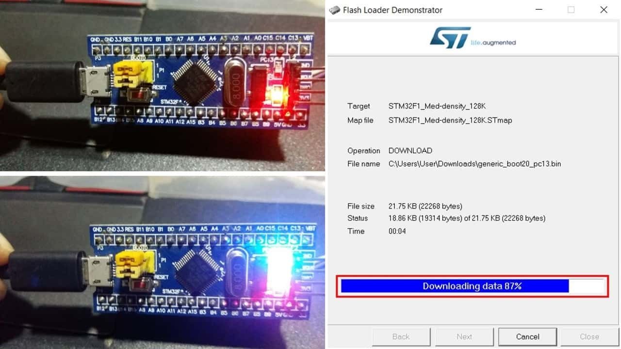
- The download process will start shortly.

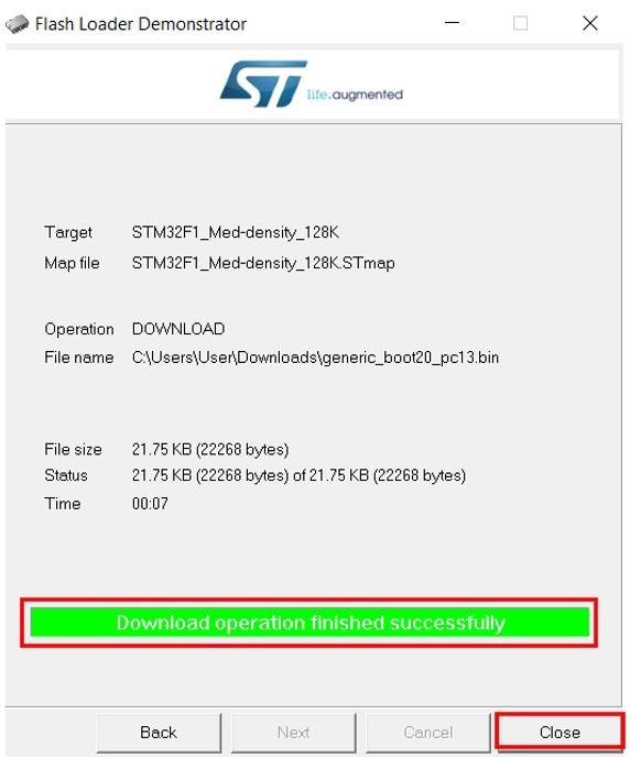
- After the STM32 is successfully flashed with the boot loader, you will view the success message. Now click the ‘Close’ button.
Now lets move to the next step. We will now have to setup our Arduino IDE for STM32 Blue Pill programming as well as install the required drivers.
Remove the USB-TTL converter from the STM32 Blue Pill and plug the Blue Pill using the USB port.
Setting up Arduino IDE for STM32
We will use Arduino IDE to program our STM32 Blue Pill using the micro USB port. Thus, you should have the latest version of Arduino IDE.
Additionally, you also need to install the STM32 plugin. First of all open your Arduino IDE and head over to File > Preferences and add the following link in the Additional Boards Manager URLs:
http://dan.drown.org/stm32duino/package_STM32duino_index.jsonNow head over to Tools > Board > Board Manager. Type ‘STM32F1’ in the search bar and press enter. Install the board package highlighted below:

After the installation is complete, you will be able to view STM32F1 Boards in Tools > Boards.

Select ‘Generic STM32F103C series’ from the board section. The Upload method is “STM32duino bootloader.”
Note that the USB port is still not discoverable at this moment. We have to install STM32 USB driver now in order for the port to be visible.

Install STM32 USB Driver
First of all download the STM32 USB Mini Driver (Download from this link). After the download is complete open the folder and navigate to drivers > win > install_drivers
Click install_drivers and the Maple DFU and Serial drivers will start installing in the command prompt:

After a few minutes, you can view that the Maple DFU driver is successfully installed.

Likewise, the STM Serial driver is also successfully installed.

Now head over to Arduino IDE Tools > Port or Device Manager to check whether the port through which the STM32 Blue Pill is connected is visible or not. Maple Mini will be written in brackets along with the COM port.

If the port is still not visible, solder a 1.5k ohm resistor between the Blue Pill’s 3.3V and PA12 pins.
Program STM32 Blue Pill through the USB Port
Now we are ready to program our STM32 Blue Pill directly through the USB port. Open Arduino IDE and head over to File > Examples > A_STM32_Examples > Digital > Blink
The basic example sketch to toggle the onboard LED after every second will open up. For STM32 Blue Pill, the onboard LED is connected with PC13. Remember to change the LED pin configuration in code accordingly.
/*
  Blink
  Turns on an LED on for one second, then off for one second, repeatedly.

  Most Arduinos have an on-board LED you can control. On the Uno and
  Leonardo, it is attached to digital pin 13. If you're unsure what
  pin the on-board LED is connected to on your Arduino model, check
  the documentation at http://arduino.cc

  This example code is in the public domain.

  modified 8 May 2014
  by Scott Fitzgerald

  Modified by Roger Clark. www.rogerclark.net for Maple mini 25th April 2015 , where the LED is on PB1

 */


// the setup function runs once when you press reset or power the board
void setup() {
  // initialize digital pin PB1 as an output.
  pinMode(PC13, OUTPUT);
}

// the loop function runs over and over again forever
void loop() {
  digitalWrite(PC13, HIGH);   // turn the LED on (HIGH is the voltage level)
  delay(1000);              // wait for a second
  digitalWrite(PC13, LOW);    // turn the LED off by making the voltage LOW
  delay(1000);              // wait for a second
}
The following code sets PC13 to a high state for a second and then to a low state for a second. This occurs inside the infinite loop function hence causing the onboard LED to toggle after each second.
Demonstration
Choose the correct board and COM port before uploading your code to the board.
- Therefore go to Tools > Board and select Generic STM32F103C series
- Then, go to Tools > Port and select the appropriate port through which your board is connected. In our case it is COM14

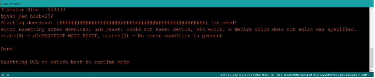
Click on the upload button to upload the code to STM32 Blue Pill. Make sure that the BOOT jumper is present at 0. There is no need to move it to 1.
The picture below shows a successful upload of code through the boot loader.
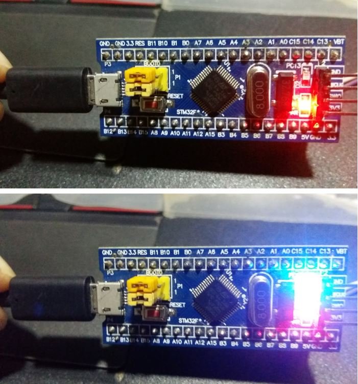
After you have uploaded your code to the board, press its RST button. When you press the RST button, the onboard LED starts blinking.
You may also like to read:
- STM32 Blue Pill GPIO Pins with STM32Cube IDE: LED Blinking Tutorial
- Push Button with STM32 Blue Pill using STM32Cube IDE – Read Digital Input Pins
- STM32 Blue Pill External Interrupts with STM32Cube IDE and HAL Libraries
- STM32 Blue Pill Timer Interrupt with STM32Cube IDE and HAL Libraries
- STM32 Blue Pill UART Communication Tutorial with CubeIDE and HAL Libraries
- STM32 Blue Pill UART Interrupt with CubeIDE and HAL Libraries
- STM32 Blue Pill UART DMA with STM32Cube IDE and HAL Libraries
- STM32 Blue Pill ADC with Polling, Interrupt and DMA
- STM32 Blue Pill Timer Input Capture Mode with Frequency Measurement Example
I have done all the steps successfully. I soldered a 1.5k ohm resistor between the Blue Pill’s 3.3V and PA12 pins too. But the port is still invisible. Only shows Maple DFU under libusb-win32 devices. What should I do?