In this Raspberry Pi Pico tutorial, we will learn about I2C communication protocol and pins featured on the Pi Pico board. Moreover, we will interface our Raspberry Pi Pico with different sensors and devices that communicate via I2C protocol and program our board to run an I2C scanner. This scanner will determine the number of I2C devices connected with the Raspberry Pi Pico.
Raspberry Pi Pico exposes 26 multi-function GPIO pins from a total of 36 GPIO pins available in RP2040 microcontroller. RP2040 chip has two I2C controllers (I2C0 and I2C1). Both I2C controllers are accessible through GPIO pins of Raspberry Pi Pico.
Prerequisites
Before we start this lesson make sure you are familiar with and have the latest version Python 3 in your system, have set up MicoPython in Raspberry Pi Pico, and have a running Integrated Development Environment(IDE) in which we will be doing the programming. We will be using the same Thonny IDE as we have done previously when we learned how to blink and chase LEDs in micro-python. If you have not followed our previous tutorial, you check here:
If you are using uPyCraft IDE, you can check this getting started guide:
I2C Introduction
I2C is also known as an inter-integrated circuit or IIC or I square C. It is a 2-wire serial communication protocol for short range data transfer applications. It is an asynchronous half-duplex serial communication protocol. Furthermore, it is a multi-master bus protocol that requires only two wires to transfer data serially which are SCL and SDA.
- SDA ( Bidirectional data line)
- SCL ( Bidirectional clock line)
It is a very popular communication protocol used in embedded projects to interface I2C based sensors, digit displays, and communication modules. Devices that want to communicate with each connect through an I2C bus. I2C bus supports multiple slave devices and multiple master devices.
Data is transferred bit by bit serially along a wire (the SDA line). Like SPI, I2C is concurrent, the output of bits is synchronized to the testing of bits by a clock signal shared between the master and the slave.
Many Sensors use this serial communication protocol to transfer their data to microcontrollers or through this protocol different slave circuits are able to communication with master circuits. It is only applicable for short distance data transmission.
I2C Pins
The distinguishing feature of I2C over SPI is that it uses only two wires to carry out communication. One wire is SCL (serial clock line) which synchronizes the transmission of data between devices and the other wire is SDA (serial data) which carries the actual data to be transmitted. These lines are open-drain lines which means these need to be connected to pull up resistors if devices are active low. Each slave device which is connected with the bus will have a unique 8-bit address.
The communication between specific devices using two wires is accomplished by the fact that each device has its own unique device ID or address and using this address; master can choose any specific device to communicate.
For example, if we configure Raspberry Pi Pico as a master device, we can connect multiple slave devices with the same bus.
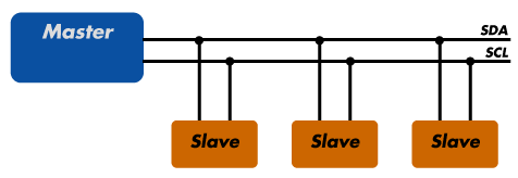
I2C Bus
I2C bus consists of multiple devices such as slave and master Slave devices. Each device connected with the I2C bus can be either in master mode or in slave mode. But only a master device can initiate the data transfer process. Usually, there is one master and one slave or multiple slave devices connected with the same I2C bus through pull-up resistors. Each salve address has a 7-bit unique address.
Slave Devices
Each slave device has a unique address that is utilized to recognize the device on the bus. In other words, slave address helps the master device to send information to a
specific slave device on the bus.
Master devices
Master devices can send and get information. Slaves react to whatever a master sends. When sending information on the bus, just a single device can send information at a time.
In short, we only need two wires for transferring data or communicating with different numbers of devices. I2C allows us to connect with multiple devices at the same time. However, you cannot use this protocol for long-distance data transferring.
For more information on I2C Communication, you can read this post:
Raspberry Pi Pico I2C Pins
Raspberry Pi Pico has two I2C controllers. Both I2C controllers are accessible through GPIO pins of Raspberry Pi Pico. The following table shows the connection of GPIO pins with both I2C controllers. Each connection of the controller can be configured through multiple GPIO pins as shown in the figure. But before using an I2C controller, you should configure in software which GPIO pins you want to use with a specific I2C controller.
| I2C Controller | GPIO Pins |
| I2C0 – SDA | GP0/GP4/GP8/GP12/GP16/GP20 |
| I2C0 – SCL | GP1/GP5/GP9/GP13/GP17/GP21 |
| I2C1 – SDA | GP2/GP6/GP10/GP14/GP18/GP26 |
| I2C1 – SCL | GP3/GP7/GP11/GP15/GP19/GP27 |

I2C controller of RP4020 chip supports the following features:
- Master or Slave Mode ( Default salve address = 0x055)
- Three speed modes such as Standard ( m 0 to 100 Kb/s) , Fast( less than or equal to 400 Kb/s) and Fast Plus mode ( s less than or equal to 1000 Kb/s)
- Transmit and Receive Buffers
- Can be used in interrupt and DMA mode
Using Raspberry Pi Pico with I2C Devices
In this section we will first connect three different I2C devices with the Raspberry Pi Pico board using the I2C pins. Then we will program our board to run an I2C scanner.
Components Required
- Raspberry Pi Pico
- SSD1306 OLED Display
- BME280 sensor
- MPU6050 sensor
- Breadboard
- Connecting Wires
First let us briefly introduce the three I2C devices that we will use in this guide: SSD1306 OLED, BME280, and MPU6050.
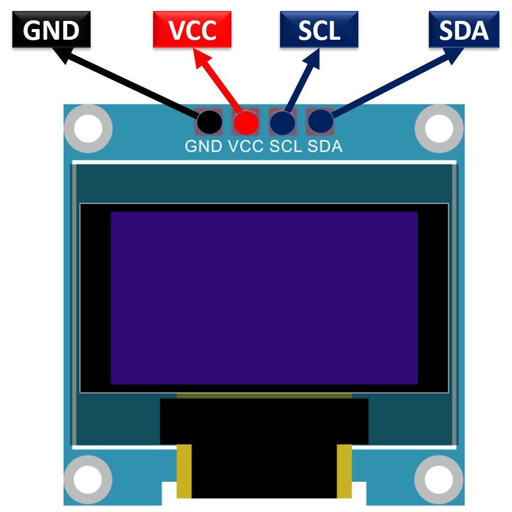
SSD1306 0.96inch OLED Display
Although there are several types of OLED displays available in the market the one which we will be using is the SSD1306 0.96-inch OLED display. The main component of all different types of OLED displays is an SSD1306 controller which uses I2C or SPI protocol to communicate with the microcontrollers. The OLED displays can vary in size, color, and shape but primarily programmed in a similar way.
Let us take a look at the OLED display which we will be using in this article. It is called SSD 1306 0.96-inch OLED display which has 128×64 pixels and communicates only via I2C protocol with the Pi Pico board. It is cheap and readily available in the market.
BME280
The BME280 sensor is used to measure readings regarding ambient temperature, barometric pressure, and relative humidity. It is mostly used in web and mobile applications where low power consumption is key. This sensor uses I2C or SPI to communicate data with the micro-controllers. Although there are several different versions of BME280 available in the market, the one we will be studying uses I2C communication protocol.
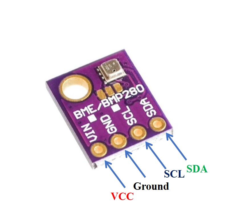
The Raspberry Pi Pico communicates with the BME280 sensor through the I2C protocol to give temperature, barometric pressure, and relative humidity readings.
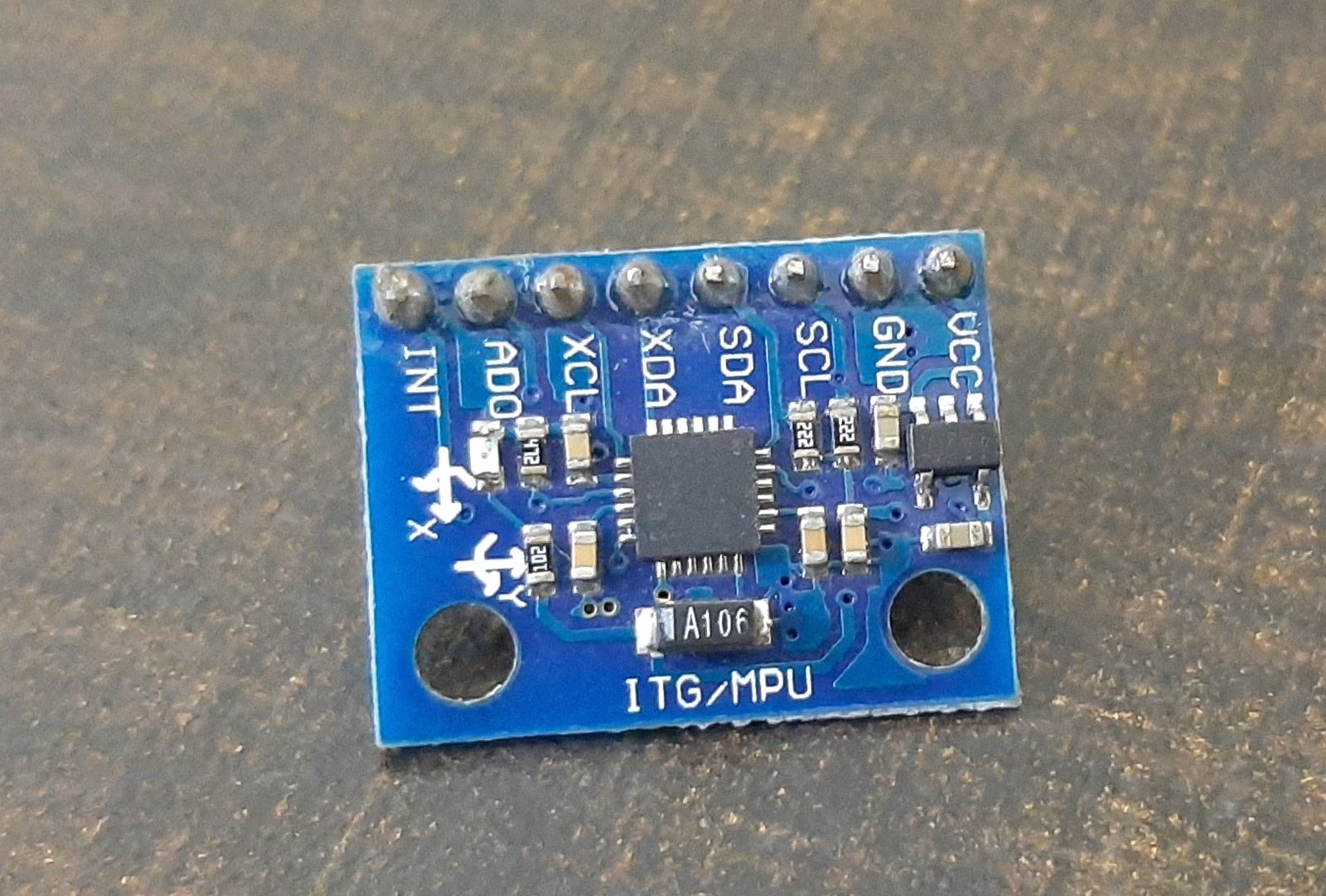
MPU6050 Sensor Module
The MPU6050 sensor module is a MEMS( Micro-Electro-Mechanical System) module that contains an integrated circuit MPU6050 IC. This chip contains a three-axis gyroscope, three-axis accelerometer, and digital motion control processor within a single IC package. On top of that, it also contains an integrated temperature sensor.
MPU6050 provides output data on an I2C bus. Therefore, we can use an I2C bus interface of MPU6050 to transfer a 3-axis accelerometer and 3-axis gyroscope values to Raspberry Pi Pico. In other words, we can use any microcontroller which has an I2C port to read sensors’ output data. There is a specific dedicated address assigned to each parameter value in the MPU6050 I2C interface. We can use these addresses to get specific values from a sensor such as acceleration, gyro, and temperature.
One of the advantages of using the I2C interface of this sensor is that we can interface multiple MPU5060 modules with a single microcontroller.
Interface Raspberry Pi Pico with OLED, BME280 and MPU6050
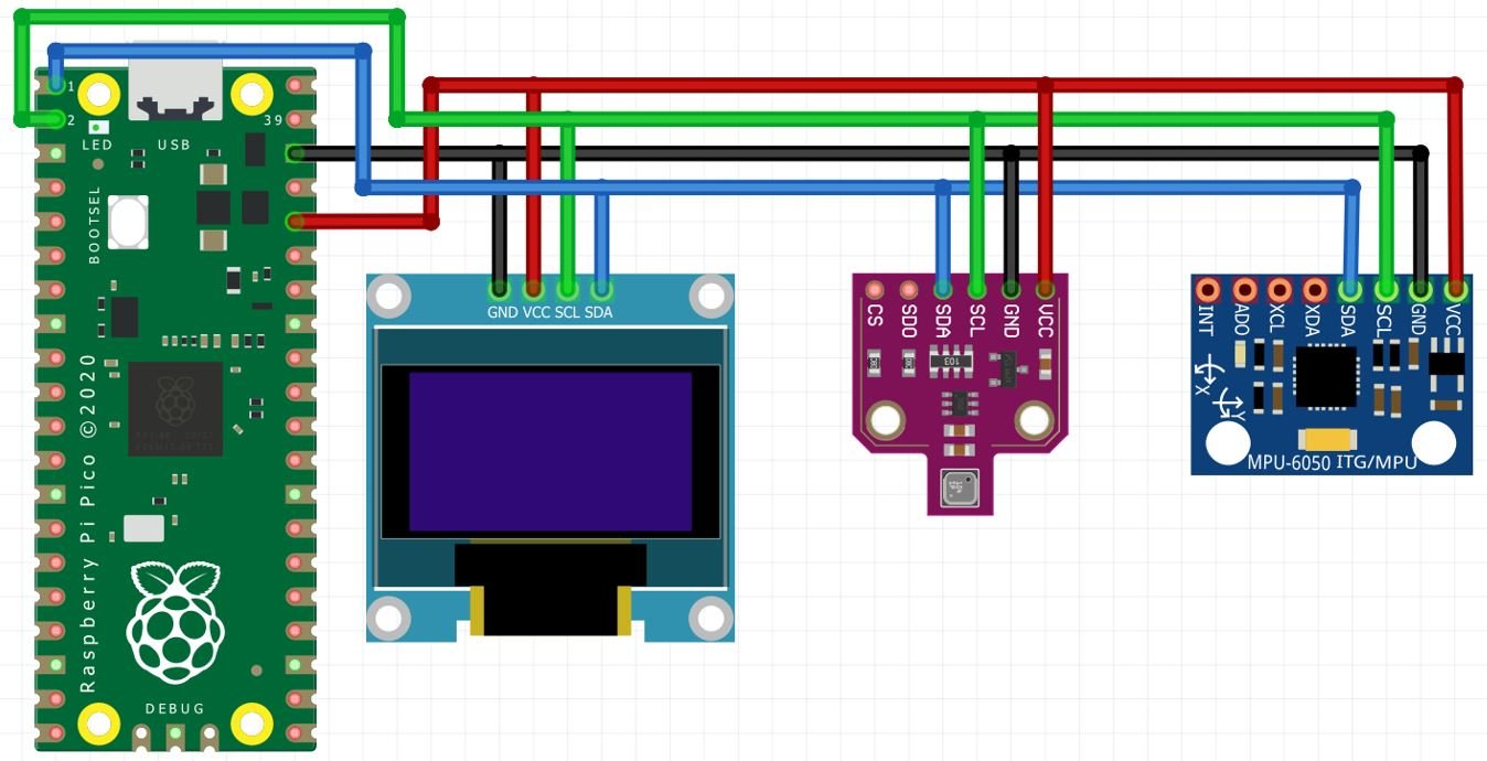
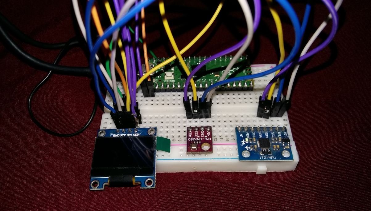
Let us see how to connect Raspberry Pi Pico with an OLED, BME280 module, and MPU6050 module together. We will use a common I2C line to connect all the devices. The Raspberry Pi Pico will act as a master, and the BME280 sensor, MPU6050 sensor, and the OLED will act as slaves.
The connections between the four devices which we are using can be seen in the table below.
| Raspberry Pi Pico | SSD1306 OLED Display | BME280 | MPU6050 |
| 3.3V | VCC | VCC | VCC |
| GP0 (I2C0 SDA) | SDA | SDA | SDA |
| GP1 (I2C0 SCL) | SCL | SCL | SCL |
| GND | GND | GND | GND |
We have used the same connections as specified in the table above. However you can use other combinations of Raspberry Pi Pico SDA/SCL pins as well.
MicroPython I2C Scanner
Every I2C device has an address associated with it. For many devices of I2C LCD, the default address is 0x27 where 0x shows hex format of the numbers. But address can be different in some cases. This address depends on the position of pads A0, A1, and A2 on the I2C controller on this device.
Now copy this code and upload it your board with all the I2C devices already connected with it.
This code will scan for any I2C devices connected with Raspberry Pi Pico and will specify the number of devices with the address in the shell console.
import machine

sdaPIN=machine.Pin(0)
sclPIN=machine.Pin(1)

i2c=machine.I2C(0,sda=sdaPIN, scl=sclPIN, freq=400000)

devices = i2c.scan()
if len(devices) == 0:
 print("No i2c device !")
else:
 print('i2c devices found:',len(devices))
for device in devices:
 print("At address: ",hex(device))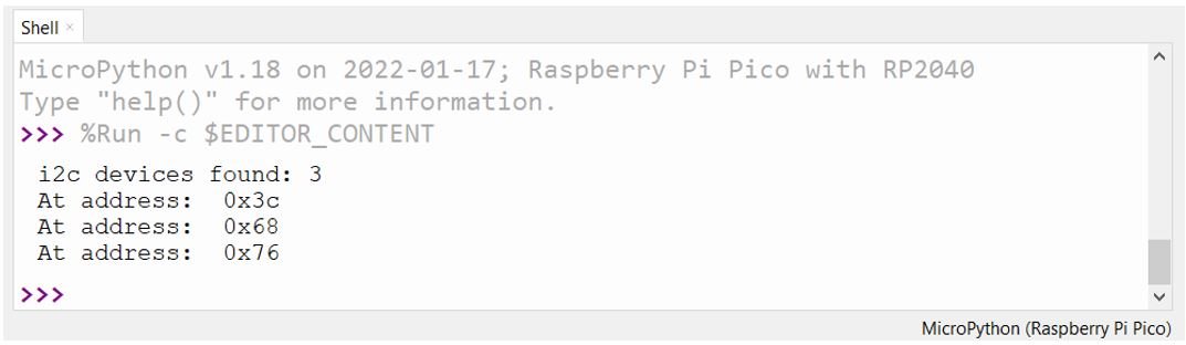
The I2C scanner identified 3 devices connected to the I2C interface. The I2C Address of OLED Display is 0x3C, MPU6050 is 0x68, BME280 is 0x76.
For details on how to read these sensor values with Raspberry Pi Pico, check these articles: