Recommended Components
The following parts are used in this article, along with a generic electronics kit that is handy for building and testing the circuit.
| Component | How it’s used | Buy on Amazon |
|---|---|---|
| RC4558 dual op-amp | The RC4558 dual operational amplifier this article covers. | Check Price |
| Electronic component assortment kit (1390 pcs) | A handy assortment of resistors, capacitors, LEDs, diodes and transistors for building circuits. | Check Price |
| Digital multimeter (AstroAI) | Measures voltage, current, resistance and checks continuity while you build and debug. | Check Price |
| Breadboard | Solderless base for prototyping the circuit. | Check Price |
| Jumper Wires | Make the connections on the breadboard. | Check Price |
As an Amazon Associate we earn from qualifying purchases. Prices and availability are accurate as of the date/time indicated and are subject to change.
RC4556 Op-Amp Pinout Diagram
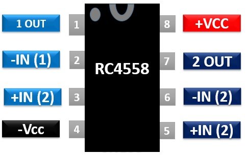
Pin Configuration Details
It consists of two operational amplifiers integrated inside the chip.- Pin2 and Pin6 are the inverting pins of both operational amplifiers.
- Pin3 and pin5 are the non-inverting pins of both operational amplifiers A and B.
- Pin1 and Pin7 give the amplified outputs.
- Pin4 and Pin8 are the voltage supply connections through which IC is powered.
RC4558 Dual Op-Amp Features
- RC4558 is a general-purpose dual operational amplifier chip.
- Outputs are protected against short-circuits and have an internal frequency compensation which provides stability without using any external components.
- Its operation is specified in range of -15V to +15V.
- It has a very high common-mode rejection ratio of 90 dB and the common-mode input voltage is typically ±
- Consumes very low power and has a supply current of 6.5mA.
- Low noise input transistors.
- Unity gain bandwidth of 3MHz which is a frequency with which the IC with unity gain can operate without distorting an output signal.
- The temperature should lie between 0°C to 70°
- It can operate as a single supply operational amplifier or as a dual supply operational amplifier but for reliable operation, a single supply is used.
Where to use it?
Firstly, it has an excellent channel separation due to you can replace LM741 IC by RC4558 IC in dense single 741 operational amplifier applications. Secondly, it can also be used in differential-in, differential-out and in potentiometric amplifiers applications. Thirdly, it has an additional feature of matched phase and gain which makes it well suited for applications requiring matched gain and phase channels.It is also used in voltage follower applications as it has a very high common-mode input voltage range and the absence of offset null capability. In addition to the above-mentioned uses, it can also perform basic functions of operational amplifiers under the above-specified features.How to use RC4558?
The operation of this IC is explained through a voltage controlled oscillator circuit which is given below. The voltage-controlled oscillator can be designed through two op-amps. Instead of using two op-amps, you can use the RC4558 IC. The voltage to be controlled is applied at the input pin2. Due to the network of a voltage divider connected between pins2 and 3, half of this voltage is applied at pin3.Voltage Controlled Oscillator Example Circuit
 The op-amp A will generate a triangular waveform on powering the IC. The current will flow from the 100k resistor and then discharges the 0.05µF capacitor resulting in a triangular wave at its output. This output is connected to the input pin of the op-amp B through a 51kΩ resistor. The op-amp works B as a Schmitt trigger. It monitors the input voltage. When the input voltage is above the threshold level, then it will send a HIGH signal at output and if the input voltage falls below the threshold level, the output will become zero. In this way, a square wave is produced at the output.
Alternative and Equivalent Op-Amps IC
NJM4560, LM358, MCP602, LM2904M, NE5532, OPA2228, OPA2134 and OPA2604Applications
Few applications of RC4558 are:- Square wave oscillator
- Audio Mixers
- Lamp Driver
- Voltage Follower
- DVD players