This article explains the variety of memory types and their used in PIC microcontroller devices. This will also explain the architecture of each memory space including the examples of addressing mods and code.
Recommended Components
The following components are used in this project or are helpful for building it with a PIC microcontroller.
| Component | How it’s used in this project | Buy on Amazon |
|---|---|---|
| PIC16F877A microcontroller | The 40-pin PIC MCU that runs this tutorial’s code. | Check Price |
| PICkit 5 programmer/debugger | Programs and debugs the PIC over the ICSP header. | Check Price |
| Breadboard | Solderless base for wiring the PIC and the project’s components. | Check Price |
| Jumper Wires | Make the connections between the MCU, components and power rails. | Check Price |
As an Amazon Associate we earn from qualifying purchases. Prices and availability are accurate as of the date/time indicated and are subject to change.
Memory types in microcontrollers Architecture
The microcontrollers units (MCUs) consists of three types of memory.
- Program Memory
- Data Memory
- Data EEPOM
Program Memory type
This is common which have all the microcontroller and its purposes is to store the instructions.it consist of further four different types of memory.
- ROM (Read only memory)
- EPROM (Erasable programmable read only memory)
- OTP (On time programmable)
- FLASH EEPROM (Electrical erasable programmable read only memory)
ROM
In microcontrollers first type memory is ROM and during the manufacturing process once the program codes are set in ROM that can’t be changed after the manufacturing process, therefore it is called read only memory mean just read the code but can’t be changed. Due to this reason the microcontrollers which have the ROM memory are considers best for that applications where there is no need of program change only need of program read. These microcontrollers are less expensive as compared to the microcontrollers which have the OTP or FLAS programmable memory and these are ordered in large quantities.PIC16CR65 and PIC16CR72 are the examples of microcontroller which have the ROM memory and denoted by “R” in part number.
EPROM
The second type is erasable programmable read only and this is used in two different type of packages. When EPROM is used in ceramic package with quartz window then microcontroller can be erased the program many times by using ultraviolet eraser and erase time depends upon the intensity of light. Normally the erase time is in between 5 and 30 minutes. In this the microcontroller can also reprogrammed the program. It is very expensive due to the high cost of the windowed ceramic package.PIC16C74B/JW EPROM microcontroller are available in market and “JW” is denoted by windowed package.
OTP
The one-time programmable memory used the same type of die as the EPROP windowed packaged devices. Its packaging makes it unique. These microcontrollers are in an opaque plastic packing and its program can’t be erase through ultraviolet light. The OTP devices are first transfer to customer side then these are programmed therefore these devices are called one time programmable. These are lowest cost devices such as PIC16C72A/P and PIC16C74B/SO are the OTP devices
Flash EPROM
This the type which provides the alternate flexibility because its program can be erased electrically and also reprogram in few seconds. It’s no need of any ultraviolet light to erase the program. Once the program is erased the program can reprogram with new code. The devices which have the flash memory can also be self-program by using some special sequence of instructions. These devices also contain a small amount non-volatile data EPROM and that can be written thousands of time. PIC16F77 and PIC16F877 are examples of microcontroller which the flash memory. In these devices “F” is denoted by part number
Program Memory Architecture
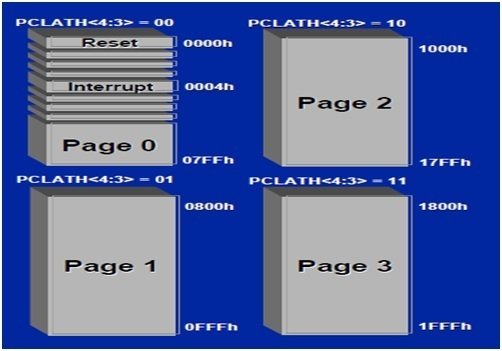
The program memory architecture is explained here with some examples such as a program memory of 14-bit microcontroller which has a data limit of 8K words and each word has a single 14-bit wide instructions. In this condition the program is divided into 4 pages and each have 2K words shown in figure
In this example the microcontroller uses the data memory to move the data among the pages. The PCLATH register is used to select the next the page where the instruction would be executing. When the CALL or GOTO instruction is executed then the PCLATH<4:3> is used to select the page branched to. WhenPCL is modified with the user code PCLATH<4:0> then PCLATH<4:0> is used with PCL to form the full PC address for executing the next instruction. In figure 1 you can see the page 0 have the Reset vector at location 0 (000h). After pushing the reset, the code starts executing at the reset vector. Usually the first two instructions set PCLATH are used for correct program page and the third instructions that is GOTO is used for code executing in another branch of program memory, otherwise a littler useful code can be used at the start of program memory if the interrupts are used. During the code executing when the interrupt is occurring then the next instruction address is fetched and saved in stack.
Page Size Limit and Absolute Addressing

The size of the program page is dictated on number of addressing bits which are encoded into branch instructions like CALL or GOTO instructions. The branch instructions first three bits indicates that this instruction can be modify the program counter. If we talk about the CALL instructions this also indicate the return address and the remaining 11-bits are loaded into 11 least significant bits (LSB) of program counter, these 11 bits for addressing allows up to 2K of address. This defines the program memory page size and the devices which have up to 2K program memory, the 2 most significant bit (MSB) of program counter is maintain clear for keeping PCLATH clear. The devices which have 4K of program required 5th-bit in PCLATH for keeping clear, while for operating in 4-bit the pages 1 or 2 are selected and the devices with 8K of program memory required 4th and 5th-bits in PCLATH to select 1 and 4 pages. Because the whole address is entirely defined using PCLATH and address is coded in instruction therefore we can say we are using absolute addressing shown in figure 2 with PSLATH register.
Data Memory
This is also a common in all the microcontrollers. Its consist of general purposes registers referred to as GPR and special function registers referred to as SPR. The data memory is divide into 4 banks and each banks having a length 128 bytes. For access to each bank the bits PR1 and PR0 of status register needs to be accessed. The special function register controls the various aspects of microcontroller depend upon the process architecture of microcontroller. It controls the following functions of controller such as input, output and peripheral control, Timer, program counter, stack pointer, stack limit, condition codes and processor status. The general purpose registers store the transient type data. For example, when the program is interrupted in its state then that value of address register, instruction register or program counter is saved in general purpose register.
Data EEPROM Memory
In addition of program and data memory some of the microcontrollers have third type of that is called data EEPROM . This is nonvolatile its data can be written in many times.
Processor Architecture
Here we take a look on the microcontroller processor architecture. It controls the structure and memory size ultimately it controls the operational speed of microcontroller. The microcontroller has two most common architectures first one is Von Neumann architecture and second one is Harvard architecture.
Von Neumann Architecture
The microcontrollers which have Von Neumann architecture have only a single memory space. This single space stores both the data and program instructions. Due to this reason the several instructions must be occur from a single memory spaces that is called fetches. The instructions which executes again and again required a several fetches to fit in a single memory space. In this condition first fetch retrieves the CPU instructions and the additional fetches retrieves the data, which is required for program instruction. By doing this decreases the bandwidth of microcontroller, because the date fetches must be wait until the program fetches instructions has completed. This is called Von Neumann bottleneck. Shown in figure 3
Harvard Architecture
PIC microcontroller units use the Harvard architecture because these microcontrollers have separate data and program memory. Therefore, in pic microcontroller units the fetching of instructions and fetching of data executes simultaneously in a single fetching operation results increased throughput. This architecture also has another advantage that it program and data bus can be tailored with performance requirements. Its data bus is always being 8-bits wide but the microchip offers the microcontroller, which have 12-, 14-, 16-bits program memory width. Increasing the width allows greater no of instructions to be fetch but still the fetching operation is in a single fetch operation.