This tutorial is an introduction to ULN2003. We will see the features, applications, pinout, and details of all pins and one example at the end of this guide on ULN2003. It is also used as a relay driver.
Why we need UNL2003?
Microcontroller and Microprocessor have an internal program or as we can say a set of functions, which control the voltage at the output and input pins of a single Control Unit. These control functions also help us to generate the timer, PWM, interrupts, and switching method internally without affecting the whole controller circuit. The issue of generating multiple functions was solved by a simple controller and processor.
Now the problem was how to control and minimize the circuit of high voltage DC devices. There was a wide usage of High voltage DC motors due to its energy efficiency. A logical circuit with Darlington transistor (NPN) was used to control the High DC load approximately equal to 50V and 500mA. This circuit could only be used for a single load. To solve this issue an IC name ULN2003 was introduced.
ULN2003 Introduction
ULN2003 comes with multiple functions. It has seven Darlington transistors installed which could help to control 7-Loads at the same time. It comes with 16 pins and multiple packings like SOP, PDIP, TSSOP or SOIC. This could help the user to install the IC with any circuit without taking too much space as a transistors circuit. The output power source could apply separately to all the outputs but the input will be the same as all microcontrollers and microprocessors.
The voltage range for any load is 50V but the current range is 500mA which could be increased by combining the multiple output pins. ULN2003 comes with internal safety protection from back emf. It has an internal flyback protection system which gives protection to the device.
Pinout of ULN2003 IC
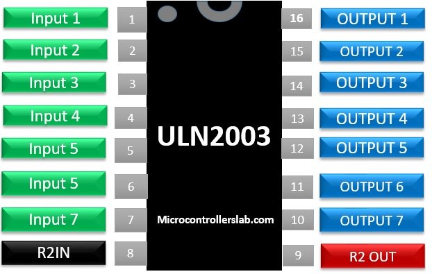
PIN CONFIGURATION Description
| Pin1 (Input 1) | These all are the input pins used to control the output pins. If Input logic is High (5 Volts) then there will be Output otherwise not. Input 1 will affect the Output 1. Input 2 will affect the Output 2 and that will go on till the Input 7 and Output 7. |
| Pin2 (Input 2) | |
| Pin3 (Input 3) | |
| Pin4 (Input 4) | |
| Pin5 (Input 5) | |
| Pin6 (Input 6) | |
| Pin7 (Input 7) | |
| Pin8 (GND) | GND pin will be used as a common ground with both the Ground of the output power source and an input power source. |
| Pin9 (COM) | Common pin used for multiple functions. It is mostly known as test pins to turn on all the outputs. In some cases, it is also used as an inductive load. |
| Pin10 (Output 7) | Output pins are the common ground within the ULN2003. Attach any load within 50V and 500mA from the outside to the Output to make the load functional. |
| Pin11 (Output 6) | |
| Pin12 (Output 5) | |
| Pin13 (Output 4) | |
| Pin14 (Output 3) | |
| Pin15 (Output 2) | |
| Pin16 (Output 1) |
FEATURES of ULN2003 IC
- It is able to handle the high DC voltage range of about 50V maxima
- It comes in another version with a voltage range of 100V.
- The current handling system is also 500mA for each input.
- The range of current could be increased by using the two pins for the same load.
- Comes with an internal clap diode to protect the device from Back EMF Protection
- ULN2003 has an internal flyback system protection and a pin too which can be used for an inductive load.
- We can control by any low voltage device like Arduino, Microprocessor or any other controller or IC.
- It is available in all kind of packages like SOP, PDIP, TSSOP or
- ULN2003 output is compatible with all the TTL and 5-V CMOS logic
- It operates without using any power source attached directly to it.
WHERE AND HOW TO USE ULN2003?
ULN2003 could be use any point where we need to control the high DC volts approximately 50V. To use this IC there are some rules which we need to follow to make it work perfectly. Attach any IC or Controller as an Input Source to provide the logical signal to the Input Pins. Then Attach the one end of the load with the output pin. Attach the other end of the load with the Power source of 0 – 50V. Then attach both Grounds of Controller and Power Source with ULN2003 Ground pin to keep in sync with the ULN2003. There is a pin as COM (Pin 9). Attach this pin with the ground through a button.
Proteus Simulation
This button could be used to bypass all the pins and could produce the output. In the case of inductive load protection, this COM pin will be effective for IC safety. The power source of each motor could be different, but the ground should remain common.

APPLICATIONS of ULN2003
- 7-relays can be controlled with a single ULN2003
- It is mostly used to control the stepper motor.
- Inductive loads are also easy to control by using ULN2003
- High load LED Bulbs can be controlled through it.
- Efficient to use Logic Buffer in mostly Digital Electronics.
- It has wide use as a torch sensor with the microcontrollers.
EXAMPLE to Control Multiple loads
We could handle multiple devices with this single device. Just attach the different loads with a different power source with ULN2003. Then Connect each load with a different power source. After that Common the ground with IC. Each Input pin controls each output. Now turn that device on which need to be on by applying High Logic on that input. To test all the pins at the same time or turn on all the devices at the same time Apply High logic at that input. During using ULN2003 always keep in mind that all the power and controllers Ground should be common with ULN2003. If Ground will not common with ULN2003 than it will have no control over the output.
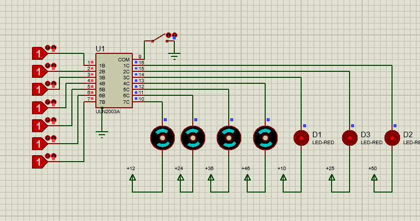
Figure 3: Multiple loads with a single IC
ULN could control multiple devices at the same time or it can also control each device at a different time too. The usage of ULN2003 is easy but due rules and regulations of every IC ULN2003 also need to be followed by its requirement. If a user is not following the rules than it could get burn due to the inductive load or any other power circuit issue. If it isn’t burned than you are lucky and change the pins according to the above, we mentioned.
Tutorials and Projects
You can refer to this guide :
- How to use ULN2003 as a relay driver circuit
- Microcontroller interfacing to relays using ULN2003
- INTRODUCTION TO ULN2803 – relay driver IC
- ULN2803
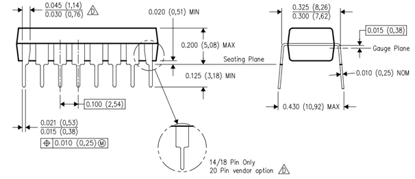
DataSheet
UNL2003 2D Diagram
I think you are using the common pin incorrectly in fig 3! It is not ground!