What is A3144 Hall Effect Sensor? Hall effect sensor is a such type of integrated, non latching sensor which is widely used for identifying the magnet pole polarity. It’s one side identify one magnetic pole such as positive magnetic pole and other side identify other one magnetic pole such as negative magnetic pole. There are two main types of hall effect sensors are available in market, first one has an analog output and second one has digital output. But here we shell only talk about A3144 Hall Effect Sensor which gives digital output. This hall effect sensor is smaller in size, consume less power and easy to interface with any type of controller.
It has so many applications such in automation system for measuring speed ,in position sensing for detecting magnetic objects, in BLDC motor for detecting it magnetic pole and in magnetic door alarm system etc. These sensors are easily available in market or on online shops. A3144 Hall Effect Sensor is shown in figure 1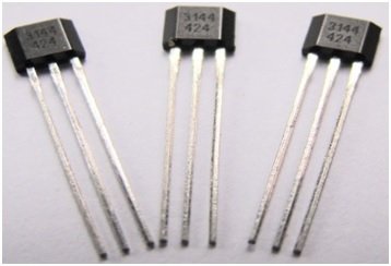
Figure A3144 Hall Effect Sensor

Pin Configuration of A3144 Hall Effect Sensor
Every A 3144 hall effect consist of three pins which are shown in figure 2. From these pins ,first pin is power pin and is used for power on this sensor. 5V dc voltages are used for power on this sensor. Second one is the ground pin and is used for supplying ground to this sensor. Similarly, third one is the digital output pin and it is connected with interfacing controller such microcontroller or Arduino etc. But a pull up resistor whose value 10k ohm is mandatory between pin 1 and 3 for keeping the output high, during when there is no any magnetic field. Similarly, a capacitor whose value 0.1μF is mandatory between pin 2 and 3 for filtering the digital output because a noise may be coupled with this digital output.
Figure 2 Pin Configuration of A3144 Hall Effect Sensor
Working Principle of A3144 Hall Effect Sensor
Every A3144 Hall Effect Sensor consists of a material which have a magnetic field, but the charges of this magnetic field are not in active position. These charges are come into active position when voltages are applied at its input pins. Similarly, when beam of charge particles is passes through this magnetic field then a force acts on these particles and beam is reflected back to straight path. This beam is actually a current carry conductor. So, two planes are formed through this whole process means first one plane with magnetic field and second one plane with deflected back beam or current carrying conductor . As result, first one plane has positive change and second one plane has negative charge. The voltages between these two planes are called hall effect voltages. If the force between current carry conductor and magnetic field is same, then the separation between these two planes will be stop. Means there is no any current change then this hall voltages measures the flux density.
How to Interface A3144 Hall Effect Sensor with Arduino Board
For checking the magnetic flux through hall effect sensor, a controller is necessary for interfacing purposes with hall effect senor. So here we shell tell the user how interface the hall effect sensor with Arduino board. For interfacing this A3144 Hall Effect Sensor with Arduino board wiring connection are made according to figure 3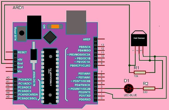
Figure 3 Interfacing of A3144 Hall Effect Sensor with Arduino Board
According to figure 3 hall effect sensor is powered up though Arduino board and one LED is also connected at the output of Arduino board for checking the presence of magnetic field means this LED would be turned on during the presence of magnetic field. After making whole connection a simple logic program is written by using Arduino library. Then this logic program is up load in Arduino board with the help of Arduino IDE software. For checking purposes, turn on this Arduino board . Similarly, when any magnet brings near to hall effect sensor then this sensor senses this magnet and gives the logic high signal to Arduino board which turns on the LED .
Alternative Sensor Module
APDS9960, BH1750, VL53L0X, DHT22, LM35, TLE4999I3, CCS811, BMP280, HC-SR505, MQ137, TMP36, PT100 RTD, Color Sensor TCS230, Flex Sensor, Heart Rate Pulse Sensor, BMP180, MPU6050, Infrared Obstacles Avoidance Sensor, shock sensor module, MQ-2 gas sensor, rain detector, Soil Moisture Sensor YL-69 or HL-69, flame sensor, Hall effect sensor, DHT11, MPX4115A, adxl335
Where is the Code?