Esp8266 based home automation system project is designed to control home devices using Wi-Fi through a website or any android app which has internet connection. As you I have already posted a project on Bluetooth based home automation system and gsm based home automation system. Both these embedded system projects have limitation of distance and availability of network. For example in case of hc 05 based project, user should be in pre defined range of Bluetooth, otherwise they will not be able to switch on and switch off their devices and in case of gsm based project, user should have network connection as well as balance available in their sim. I have also posted a project on tv remote control home automation system which again has limitation of distance. Because IR communication range is also limited. But with this Esp8266 based home automation system, you can control your home devices from any corner of world unless your system and you have internet connectivity available.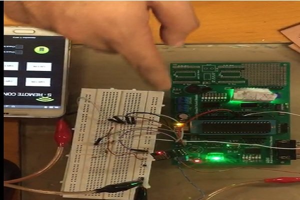
Esp8266 based home automation system components
Followings are the components used in Esp8266 based home automation system:
- PIC18F452 microcontroller : PIC18F452 microcontroller is used in this Esp8266 based home automation system. Pic microcontroller is used to send commands to ESP8266 and it is received commands from ESP8266. Microcontroller turn on or turn off loads based on received commands from ESP8266 wifi module. pic microcontroller is interfaced with ESP8266 using serial communication. Both ESP8266 and pic microcontroller communicate with each other through serial communication.
- ESP8266 (Wi-Fi module) : This is very cheap and inexpensive wifi module. It works on UART communication and it is very easy to connect this module with internet.
- RELAY Module: Four relays are used in this project to control four loads. you can learn about relay interfacing with microcontroller and how to to use relay driver.
The following project entails the user to connect to various different devices through Wi-Fi thereby functioning them through wireless means. The Wi-Fi module receives a signal wirelessly via a cellphone and then transmits it through its transmitter to the receiver of the microcontroller which in turn interprets the signal and sends a signal to the corresponding port accordingly which are initialized as outputs. A relay is used through relay interfacing for those devices which draw a larger current.
ESP8266 configuration Esp8266 based home automation system
The basic working of the project is as follows:
A USB to serial bus was used to initialize the Wi-Fi module’s initial settings for instance the baud rate was initialized to 9600bps and the CWMODE of the module was set to mode 3.
ESP8266 was initialized via the following commands:
AT
AT+CWMODE = 3
AT+CIFSR
AT+CIPMUX = 1
ESP8266 was then connected to the mobile hotspot by the following commands:
AT+CWLAP (returns the list of the available Wi-Fi networks available)
AT+CWJAP = “SSID”, “password”
Once configured, the module was then connected to the microcontroller based on the above described
Circuitry i.e. the transmitter was connected to the receiver of the microcontroller and the receiver was connected to the transmitter of the micro controller. The module receives a signal wirelessly through a cellphone. It sends a signal in the form of a string of characters to the UART (Universal Asynchronous Receiver Transmitter) terminal of the microcontroller. The string received was then compared to check for which button was pressed through the cell phone by preloaded strings and then sends a high signal to the port bit which corresponds to the string. In this way, a device that is connected to one of the output ports of a microcontroller is turned on and off wirelessly through a Wi-Fi module that is configured at the same IP address as that of the mobile phone.
Basic Concept behind interpreting the signal received at the UART terminal and analyzing it to turn on the specific device:
Every time a signal is received at the UART terminal, it is stored in the form of a string of characters: ‘0 Connect, 0 Closed, 2:1’ for the first key which turns portb.b0 = 1 and similarly for portb.b1 = 1, the string received takes the form of ‘0 Connect, 0 Closed, 2:9’. Following this analyses, the string was compared on for every character which are the same until the third last character ‘2’ is received after which a variable state is set as 1 which in turn sets state = 2 since the next character is ‘:’.Following this the next character received at the UART is the distinguishing character which is compared in the if conditions written above and in this way the corresponding bit of the port is activated.
Circuit diagram of Esp8266 based home automation system using wifi
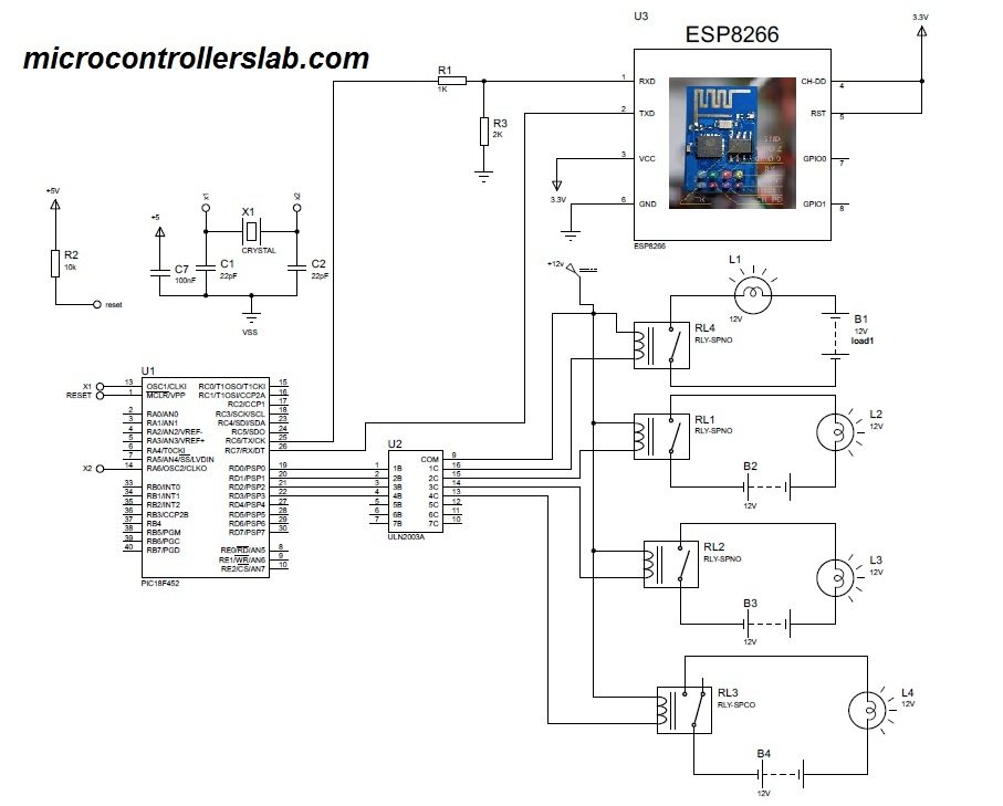
ESP8266 was connected to the microcontroller according to the above pin configuration. RX was attached to the TX pin of microcontroller which is D6 and the TX pin of ESP8266 was connected to D7 pin of the microcontroller which is the receiver. Ground of the microcontroller and ESP8266 was made common. Since ESP8266 operates at a VCC of 3.3V hence a potential divider was used to draw a voltage of 3.3V by using 3 resistors in series. The remaining pins were then grounded. The receiver of the module was also given a voltage of approx. 2.5-3 V using the same potential divider circuit.
Video demonstration of esp8266 based home automation using wifi
Relay Interfacings:
The above design indicated how when a high is received the respected transistor switches on and results in the relay being turned on which results in the port bit to be activated.
PCB design of Esp8266 based home automation system
Our project was divided into two PCB’s whose proteus design is attached above. The first PCB is used to operate the microcontroller. A voltage regulator was attached to the VCC terminal so that the voltage at the VCC of the microcontroller remains stable and does not exceed 5V. A crystal external oscillator of 11.059Hz is also used that is attached in the PCB. The voltage divider circuit as explained above is also implemented on the PCB with the resistors soldered onto a Vero board followed by approximate voltage of 3.3V to the receiver of the Wi-Fi module. The second PCB is used for relay interfacing in which Bipolar Junction Transistors are used as switches. The respective proteus design is attached above.
The respective ares designs are attached below which were used to design the hardware of PCB.In lieu of the recent advancements in technology, we’re living in a world which operates through wireless means. Implementation of actual physical wires to send and receive commands has become nearly obsolete. The following project is one example of using a Wi-Fi module to operate regular home appliances wirelessly.
बिलाल मलिक जी मेरा sp सर्वर से कनेक्ट नहीं हो रहा क्या करूं कृपया मेरी समस्या का समाधान करें
Hi. There is no code included. Is that intentionallly left out for wirhout the code the tutorial is meaningless.
Devnode.
WIFI Based Home Automation for Security and Households
A newly build housing society wants to provide the residents of society with optimal level of security and surveillance through automation at gateway and in-house level. The core requirement is to identify the resident identification and the carriage of same after scanning. The other aspect of this project is to detect and search for house hold goods easily using technology.
Scope of the System:
WIFI devices of equal compatibility to get installed at certain levels.
The Topology should be clear in all aspects considering loop holes or deadlock.
The allocation and de-allocation of rights/privileges should be transparent to all users of the colony.
The scope of home automation is limited to 20 houses.
QoS (Quality of Service) should be monitored well to ensure reliable communication in the system (with respect to authorize entry and goods).
Availability of resource is the core aspect of this project e.g. Accessibility and Integrity of network devices. (Must respond in any case)
solve it please
Could you please send me the entire project with the code and the way to interface the microcontroller with ESP8266???
Could you show us how to interface the ESP8266 with the microcontroller and share us the code used ?
Could you please send me the entire project with the code and the way to interface the microcontroller with ESP8266???