Tv remote controlled home automation system using pic microcontroller. With the help of a TV remote, we would be able to control different loads. Each button on the remote will have different functionality i.e. will turn ON/OFF different loads .TV remote will send a unique/different IR signal on each button press. TSOP (IR Receiver) will catch the signal and output a binary waveform (unique for each button).This waveform will be decoded by the PIC 18 (microcontroller). The result (of decoding) will indicate which button is pressed and hence will be used to perform different functions. So this project is about Tv remote controlled home automation system using pic microcontroller. Pic microcontroller will receive IR signals from TSOP IR receiver and take respective actions to control loads through relay interfacing.
Block diagram of Tv remote controlled home automation system

Circuit diagram of Tv remote controlled home automation system
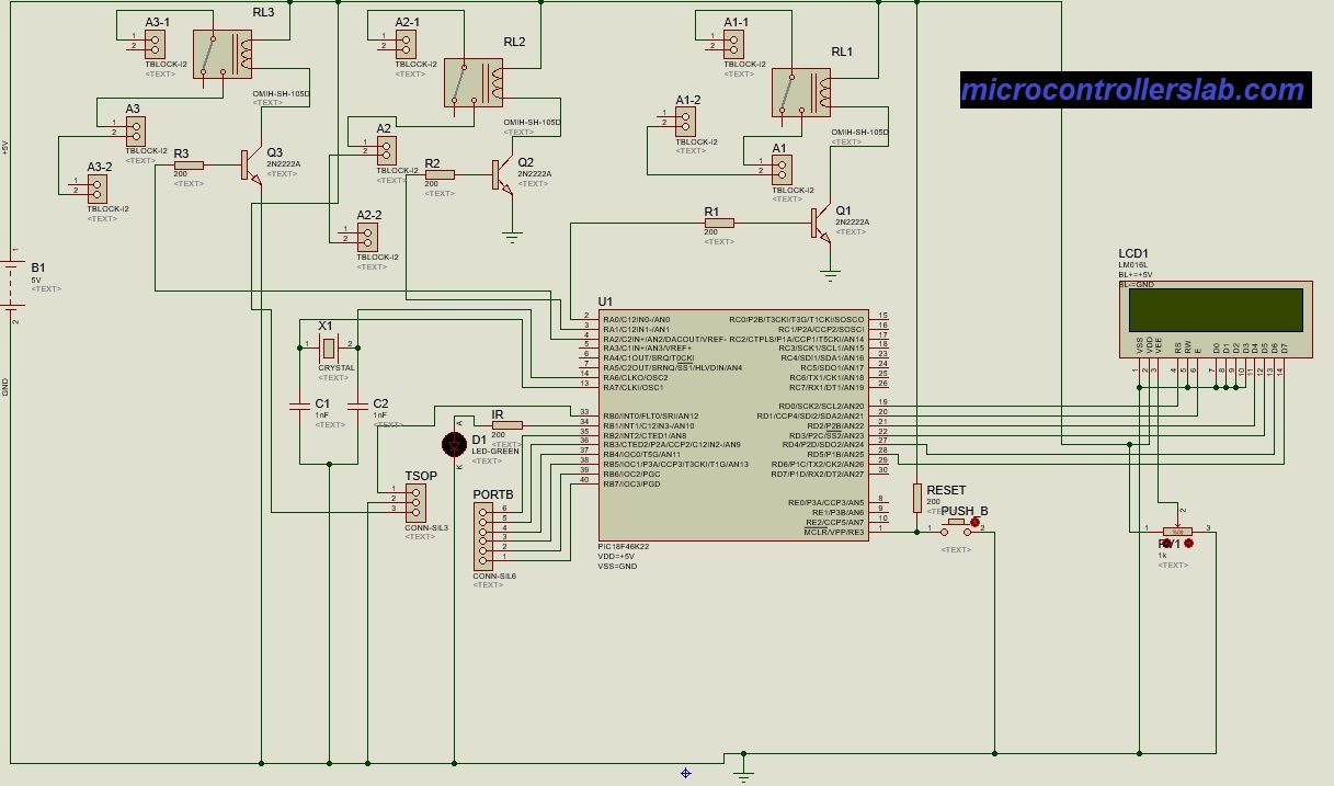
As seen from the block diagram and the proteus screenshot, the circuit will be in idle state until we press a button of the remote. As soon as we do that, IR receiver (TSOP) will detect the signal and output a binary waveform. The output waveform will be different for different infrared data communication protocols. In our case, our remote used SONY protocol. It is to be noted that TSOP outputs the waveform which it receives from the remote (I.e. it does not produce a waveform of its own). And for each button there is a different waveform produced, but type of the waveform (i.e. the protocol to which it belongs to) remains the same (in our case protocol is SONY). It is also to be noted that the protocol type solely depends on the transmitter (in our case TV remote), and TSOP just outputs the waveform. That is, different transmitters will send out different protocols.
working of Tv remote controlled home automation system
So, this waveform is sent to the microcontroller (PIC 18), which decodes it and retrieves the Address bits and the Command bits from the whole waveform. The Address bits indicate which device is sending the signal and hence remain same for one device. In our case the device was a TV remote and the value in decimal (for Address bits) was 1. The Command bits indicate which button is pressed and gives different values (in decimal) for different buttons. Using these command bits, we can assign different actions/functions to different buttons. Our Protocol was 12-bit SONY protocol with 5 Address bits and 7 command/data bits. The Picture of the SONY protocol is attached at the end of the explanation.
For different buttons pressed, we changed the status of different output PORTS of PIC. Each output port is connected to the base of a 2N2222A transistor. And this transistor drives/switches the relay when output (at the PORT) is high. Relay cannot be directly connected to PIC, since microcontroller cannot source enough current do drive the relay. So when the relay switches or is energized, the desired load or appliance turns ON. And when the output (at the PORT) goes low, the relay switches back (i.e. no current flowing in the coils, hence is not energized anymore), thus the load or appliance turns OFF.
Below is the description of the protocol which our remote was sending:

Video of TV remote controlled home automation system
Code Tv remote controlled home automation system
The decoding of the waveform is done by simple use of time delays, since we know the duration of the different states of the waveform (as shown in the protocol description diagram). The code is highly commented and is self-explanatory. Everything in green are the comments (for better understanding of the code).Only the 2 ‘defines’ used,(located) just above the main, need to be explained.
#define bit_set(d,b) (d|=(1<<b))

Above line is equivalent to the ‘set_bit’ function defined below:

set_bit(variable , bit)

{

                short temp;

                temp = 1<<bit;

                variable = variable || temp;        //taking OR

}

#define bit_clear(d,b) (d&=~(1<<b))

Above line is equivalent to the ‘clear_bit’ function defined below:

clear_bit(variable , bit)

{

                short temp;

                temp = 1<<bit;

                temp = ~temp; //will invert or complement all bits

                variable = variable && temp;      //taking AND

}
so this is all about Tv remote controlled home automation system. I have tried to provide you all the details of project and coding. Complete code for this project is not free of cost. If you want to purchase code. Contact me at microcontrollerslabhub@gmail.com