4N25 belongs to one of the most famous families of optocouplers. Other optocouplers that have almost similar features are 4N27, 4N27 and4N28. We will discuss all these optoisolators in a single article because they have the same function and pin diagram. All these optocouplers consist of a photodiode and a phototransistor. Gallium arsenide material is used for an infrared light-emitting diode. The phototransistor is made up of a monolithic silicon material. Both photodiode and phototransistor are so coupled that when infrared light of photodiode falls on the base pin of a phototransistor, it turns on by forming an electrical close switch like connection between collector and emitter pins.
4N25 Pinout
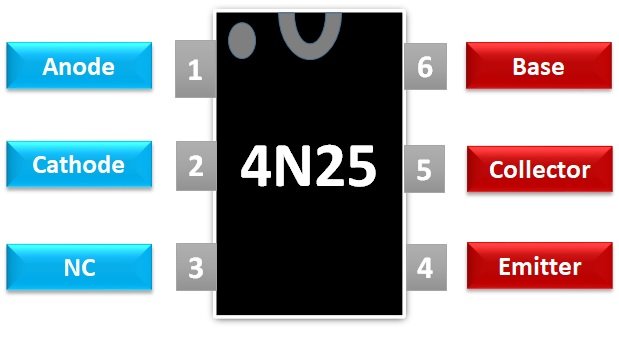
The pin diagram of 4N25 is given below. However, this pin diagram is also exactly similar for other same series of components such as 4N26, 4N27, and 4N28.

It comprises of six pins and one pin is unutilized that is a pin three. The table below illustrates the functionality of each pin shown in the above pin diagram.
| Pin 4N25, 4N26,4N27, 4N28 | Function |
|---|---|
| Anode (1) | Anode terminal of LED |
| Cathode (2) | Cathode terminal of LED |
| NC (3) | No connection / Not used |
| Emitter (4) | Emitter pin of phototransistor |
| Collector (5) | Collector pin of phototransistor |
| Base (6) | Base pin of phototransistor |
4N25 Features and Electrical Specifications
- Offer high voltage isolation of 500Vrms test voltage
- Common 6-pin DIP package
- 4N25 optoisolator has very fast switching time .i.e rise time and fall time.
- Coupling capacitance between the input and output side is less than 0.5 pF
- Input side reverse voltage is 5 volts and forward current is 60mA
- The power dissipation of the infrared photodiode is 100mW.
- Collector-Emitter voltage breakdown is 70V
- Emitter based breakdown voltage is 7V
- Output side power dissipation is 150mW
- It is tested up to 5000 Vrms isolation voltage
- Switching period rise time: 2μs
- Switching period fall time: 2μs
- No external biasing power supply required to power IC
How to use 4N25
This animation depicts a simple example of an optocoupler of any type. However, we use 4N25 in this example. This circuit demonstrates LED controlling with a switch optically. At the input side, the logic signal probe provides a logic high-low signal to a photodiode. The phototransistor turns on and turns off according to a state of the logic switch.
Where to use 4N25 photocoupler?
As their name suggests, 4N25 and other equivalent optocouplers such as 4N26, 4N27, 4N28 can be used to provide electrical isolation between two circuits. In other words, it is used to make an electrical connection between two electrical circuits through photonics signals such as infrared LED and phototransistor. In short, 4N25 optocoupler is used in applications where to want to isolate electrical circuits from each other. For further information, check examples that are given in the next section.
4N25 Examples
- Consider a microcontroller-based project where you want to control a 220-volt lamp with ESP32. Now you have two different electrical devices operating at different voltage levels. One is a microcontroller that gives a control signal to the lamp through some electronic interfacing circuitry and microcontrollers operating voltage is 5 volts dc. Another electrical device is a 220-volt lamp that works on the high voltage that is 220 volts ac supply. 4N25 optocoupler can be used to isolate the low voltage side from the high voltage side. However, you can still transfer an electrical signal between both sides through a 4N27 optoisolator.
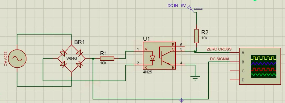
- It can be used for Zero crossing detection applications using a microcontroller. The circuit diagram of the zero detector circuit is shown here.

- It can be used for controlling speed of high voltage dc motor.
- AC load interfacing with microcontroller
You may also read this optocoupler interfacing with a microcontroller article to know more about its practical applications.
4N25 Applications
- AC power mains detection.
- AC voltage measurement using a microcontroller
- Solid-state relay
- Switch-mode power supplies
- Logical common – ground isolation between circuits operating at different voltages.
- Ring detector
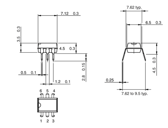
2D model
The picture below shows the 2D model and dimensions of this optocoupler.


Magnifica la informacion asi como las explicaciones