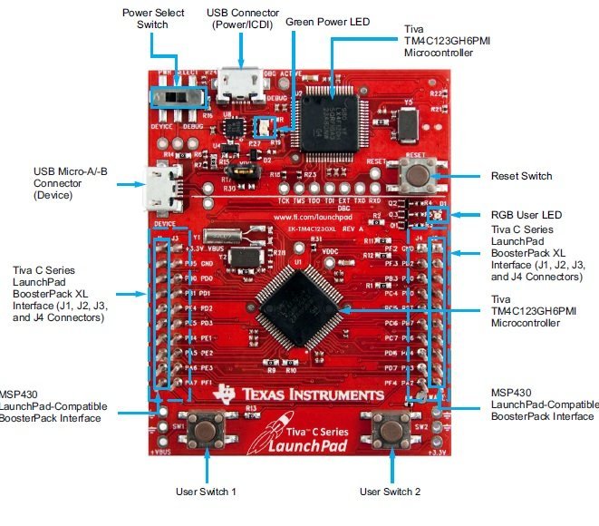
In this tutorial, we will discuss TM4C123 Timer interrupt programming ARM Cortex M4 microcontrollers. Firstly, we will discuss applications of timer interrupt with one example. We will use a TM4C123 Tiva C launchpad for demonstration purposes. It comes with a TM4C123GH6PM microcontroller. The general purpose timer module TimerA module will be configured and initialized to generate a 1s periodic interrupt. That means an interrupt handler routine of the TimerA module will execute after every one second. We can perform the operations that we want to perform inside the exception handler function.
Recommended Components
The following components are used in this project or are helpful for getting started with TM4C123 Tiva C LaunchPad development.
| Component | How it’s used in this project | Buy on Amazon |
|---|---|---|
| TM4C123G Tiva C LaunchPad | Runs the Timer1A interrupt and toggles its onboard LED | Check Price |
| Micro USB Cable | Programs and powers the board from your computer | Check Price |
As an Amazon Associate we earn from qualifying purchases. Prices and availability are accurate as of the date/time indicated and are subject to change.
General Purpose Timer Interrupt
Programmable general purpose timer modules (GPTM) of TM4C123 microcontroller can be used to count external events as a counter or as a timer. For example, we want to measure an analog signal with the ADC of TM4C123 microcontroller after every one second. By using GPTM, we can easily achieve this functionality. In order to do so, first configure the timer interrupt of TM4C123 to generate an interrupt after every one second. Second, inside the interrupt service routine of the timer, sample the analog signal value with ADC and turn off ADC sampling before returning from the interrupt service routine. Similarly, general purpose timer modules have many applications in embedded systems.
Applications
Few important applications are:
- External event measurement ( Example HC-SR04 with TM4C123 )
- Pulse width measurement
- Frequency measurement
- Motor RPM Measurement TM4C123
In the last tutorial, we learnt to use the ADC module of TM4C123GH6PM microcontroller. Complete in depth article is available on this link:
How to configure Timer Interrupt of TM4C123
TM4C123 microcontroller provides two timer blocks such as Timer A and Timer B. Each block has six 16/32 bits GPTM and six 32/64 bits GPTM. We will use the TimerA block in this tutorial.
First create a project in Keil uvision by selecting TM4C123GH6PM microcontroller. If you don’t know how to use Keil uvision, you should refer to these posts:
Include the header file of TM4C123GH6PM microcontroller which contains a register definition file of all peripherals such as timers.
#include "TM4C123.h" // Device header file for Tiva Series MicrocontrollerTimer1A Interrupt with Second Delay
In this section, we create a timer interrupt of 1Hz. That means the interrupt will occur after every one second. Because the time period is inverse of the frequency. Whenever an interrupt occurs, we will toggle an LED inside the corresponding interrupt service routine of TimerA module. In short, the interrupt service routine will execute every one second and toggle the onboard LED of TM4C123 Tiva C Launchpad.
TM4C123 Tiva C Launchpad has an onboard RGB LED. Blue LED is connected with the PF3 pin of PORTF. We will toggle this LED inside the interrupt service routine of TimerA. First let’s define a symbol name for this PF3 pin using #define preprocessor directive.
#define Blue (1<<2) // PF3 pin of TM4C123 Tiva Launchpad, Blue LEDInitialize Timer 1A registers for one second Delay
First enable the clock to timer block 1 using RCGTIMER register. Setting 1st bit of RCGTIMER register enables the clock to 16/32 bit general purpose timer module 1 in run mode. This line sets the bit1 of the RCGTIMER register to 1.
SYSCTL->RCGCTIMER |= (1<<1); /*enable clock Timer1 subtimer A in run mode */
Before initialization, disables the Timer1 output by clearing GPTMCTL register.
TIMER1->CTL = 0; /* disable timer1 output */First three bits of GPTMCFG register is used to select the mode of operation of timer blocks either in concatenated mode (32 or 64 bits mode) or individual or split timers ( 16 or 32 bit mode). We will be using a 16/32-bit timer in 16-bits configuration mode. Hence, writing 0x4 to this register selects the 16-bit configuration mode. ( check datasheet 726 of TM4C123GH6PM)
TIMER1->CFG = 0x4; /*select 16-bit configuration option */Timer modules can be used in three modes such as one-shot, periodic, and capture mode. We want the timer interrupt to occur periodically after a specific time. Therefore, we will use the periodic mode. In order to select the periodic mode of timer1, set the GPTMTAMR register to 0x02 like this (refer to page 732 datasheet):
TIMER1->TMAR = 0x02; /*select periodic down counter mode of timer1 */We are using timer1 in 16-bit configuration. The maximum delay a 16-bit timer can generate according to 16MHz operating frequency of TM4C123 microcontroller is given by this equation:
2^16 = 65536
16MHz = 16000000
Maximum delay  = 65536/16000000 = 4.096 millisecond
Hence, the maximum delay that we can generate with timer1 in 16-bit configuration is 4.096 millisecond. Now the question is how to increase delay size? There are two ways to increase the timer delay size: either increase the size of timer ( 32-bit or 64-bit) or use a prescaler value. Because we have already selected the 16-bit timer1A configuration. Therefore, we can use the prescaler option.
Prescaler Configuration
Prescaler adds additional bits to the size of the timer. GPTM Timer A Prescale (GPTMTAPR) register is used to add the required Prescaler value to the timer. TimerA in 16-bit has an 8-bit Prescaler value. Prescaler basically scales down the frequency to the timer module. Hence, an 8-bit Prescaler can reduce the frequency (16MHz) by 1-255.
For example, we want to generate a one-second delay, using a Prescaler value of 250 scales down the operating frequency for TimerA block to 64000Hz .i.e. 16000000/250 = 64000Hz = 64KHz. Hence, the time period for TimerA is 1/64000 = 15.625ms. Hence, load the Prescaler register with a value of 250.
TIMER1->TAPR = 250-1; /* TimerA prescaler value */When the timer is used in periodic countdown mode, the GPTM TimerA Interval Load (GPTMTAILR) register is used to load the starting value of the counter to the timer.
TIMER1->TAILR = 64000 - 1 /* TimerA counter starting count down value */GPTMICR register is used to clear the timeout flag bit of timer.
TIMER1->ICR = 0x1; /* TimerA timeout flag bit clears*/After initialization and configuration, enables the Timera module which we disabled earlier.
TIMER1->CTL |= (1<<0); /* Enable TimerA module */Configure TM4C123 Timer Interrupt
There are two steps to enable the interrupt of peripherals in ARM Cortex-M microcontrollers. Firstly, enable the interrupt from the peripheral level ( Timer module in this case) using their interrupt mask register. GPTM Interrupt Mask (GPTMIMR) register enables or disables the interrupt for the general purpose timer module of TM4C123 microcontroller. Bit0 of GPTMIMR enables the TimerA time-out interrupt mask.
TIMER1->IMR |=(1<<0); /*enables TimerA time-out interrupt mask */Secondly, we must also enable the GPTM interrupt request to a nested vectored interrupt controller using their interrupt enable registers. Interrupt request number of Timer1A is 21 or IRQ21. Hence, it corresponds to NVIC interrupt enable register zero. This line enables the Timer1A to interrupt from NVIC level by setting bit21 :
NVIC->ISER[0] |= (1<<21); /*enable IRQ21 */You can also find the interrupt number of every exception handler or ISR inside the startup file of TM4C123 microcontroller.
Implementation of Timer Interrupt Handler function
ISR routines of all peripheral interrupts and exception routines are defined inside the startup file of TM4C123 Tiva microcontroller and the interrupt vector table is used to relocate the starting address of each interrupt function. In order to find the name of the handler function of Timer1 and sub-timer A, open the startup file and you will find that the name of the Timer1A handler routine is TIMER1A_Handler(). By using this name of the Timer1A interrupt handler, we can write a c function inside the main code like this:
TIMER1A_Handler()
{
// instructions you want to implement
}
If you want to know what are the sequence of steps ARM Cortex-M processors perform when interrupt occurs, you can read this post:
TM4C123 Timer Interrupt Example Code
This example code of TM4C123 Tiva C Launchpad generates a delay of one second using the Timer1A interrupt handler routine. Inside the main code, we initialize the PF2 pin as a digital output pin.
If you don’t know how to use GPIO pins of TM4C123 Tiva C Launchpad, read this article first:
/* This is a timer interrupt example code of TM4C123 Tiva C Launchpad */
/* Generates a delay of one second using Timer1A interrupt handler routine */
#include "TM4C123.h"   // Device header file for Tiva Series Microcontroller
#define Blue (1<<2)   // PF3 pin of TM4C123 Tiva Launchpad, Blue LED
void Time1A_1sec_delay(void);
int main(void)
{
	/*Iniitialize PF3 as a digital output pin */
   SYSCTL->RCGCGPIO |= 0x20; // turn on bus clock for GPIOF
   GPIOF->DIR       |= Blue; // set blue pin as a digital output pin
   GPIOF->DEN       |= Blue;  // Enable PF2 pin as a digital pin
   Time1A_1sec_delay();
	while(1)
	{
		// do nothing wait for the interrupt to occur
	}
}

/* Timer1 subtimer A interrupt service routine */
TIMER1A_Handler()
{
	  if(TIMER1->MIS & 0x1)
		GPIOF->DATA  ^= Blue; /* toggle Blue LED*/
		TIMER1->ICR = 0x1;          /* Timer1A timeout flag bit clears*/
}
void Time1A_1sec_delay(void)
{
SYSCTL->RCGCTIMER |= (1<<1);  /*enable clock Timer1 subtimer A in run mode */
TIMER1->CTL = 0; /* disable timer1 output */
TIMER1->CFG = 0x4; /*select 16-bit configuration option */
TIMER1->TAMR = 0x02; /*select periodic down counter mode of timer1 */
TIMER1->TAPR = 250-1; /* TimerA prescaler value */
TIMER1->TAILR = 64000-1 ; /* TimerA counter starting count down value  */
TIMER1->ICR = 0x1;          /* TimerA timeout flag bit clears*/
TIMER1->IMR |=(1<<0); /*enables TimerA time-out  interrupt mask */
TIMER1->CTL |= 0x01;        /* Enable TimerA module */
NVIC->ISER[0] |= (1<<21); /*enable IRQ21 */
}
Inside the interrupt handler function of Timer1A, we are toggling the Blue LED of TM4C123 Tiva C Launchpad. Also clears the raw interrupt flag before returning from interrupt service routine.
/* Timer1 subtimer A interrupt service routine */
TIMER1A_Handler()
{
    if(TIMER1->MIS & 0x1)
       GPIOF->DATA  ^= Blue; /* toggle Blue LED*/
       TIMER1->ICR = 0x1;          /* Timer1A timeout flag bit clears*/
}
Conclusion
In summary, configuring timer interrupts on ARM Cortex-M microcontrollers allows for precise control of time-dependent tasks in embedded systems. This tutorial covered the essentials of setting up a periodic timer interrupt using a general-purpose timer, demonstrated by toggling an LED at regular intervals. By understanding the steps of timer configuration, prescaling, and interrupt handling, you can apply these techniques to a wide range of applications, from event measurement to time-based operations. Mastering timer interrupts will enhance your ability to develop efficient and responsive embedded systems.
Other timer related articles:
- TM4C123 Timer in Input Edge Time Mode – Pulse Duration Measurement
- Frequency Measurement using TM4C123 Timers in Input-Edge Capture Mode
- TM4C123 Timer as a Counter in Input-Edge Count Mode – RPM Measurement Example
- HC-SR04 Ultrasonic Sensor Interfacing with TM4C123 – Distance Measurement Example
Other Interrupt Related Tutorials TM4C123 MCU:
Great article… Thanks, for sharing
I don’t understand why the value load into the TAILR is 64000-1. Why is minus One?. Thank you.
i copy this code and paste in my project, but the led not blinks enough 1s
Make sure you selected the correct crystal frequency from project settings.
I checked in the “system_TM4C123.c” file, and found this one “SYSCTL->RCC2 = 0x07802810;”. And in “options for target…”, Xtal = 16(MHz).
hello, thank you for the code. If I want to light different color LED which on tiva card as PF4 at different distances, how and where should I write this code?
What you meant by distance?
Hello!
First of all congratulations on the great tutorials!
I have a problem with this code and I also had a problem with the UART project.
I think it is a clock problem.
In the UART project I was only getting squares and other strange symbols on HTerm.
In this one the interrupt is never triggered. I have a breakpoint on
if(TIMER1->MIS & 0x1) of the TIMER1A_Handler().
I somehow think there is a problem with my clock configuration (which I have not changed).
The configuration wizard of system_TM4C123.c file is as follows:
RCC:
system clock divison:4
enable system clock divider: yes
enaable PWM clock divider: yes
PWM unit clock divisor:7(SysClk/64)
PLL Power down: no
PLL bypass: no
XTAL:Crystal Value 21(16MHz)
Oscillator source: 0 (main oscillator)
Internal oscillator disable: yes
Main oscillator disable: no
RCC2:
use RCC2:no
System Clock divisor: 4
Power down PLL: no
Bypass PLL: no
is there something wrong with this configuration? I am asking because I cannot think of anything else…
In case you have any other idea/recommendation, I would really appreciate it.
Again thanks a lot for the great tutorials
I finally figured out why.
The interrupt was not triggered because I am coding in C++ and I had to put extern “C”{} around the handler.
Another issue that I found out is that my micro runs at 50MHz (System clock) and the PIOSC at 4MHz (16MHz/4).
I do not know why it is setup like this, but now I adjusted the baud rate calculations and the interrupt related registers and everything works fine.
I can now move on to the rest of this amazing tutorials series.
That’s great Theo and we are glad that our tutorials helping others.
“Excellent tutorial on setting up Timer interrupts with the TM4C123! I found the step-by-step guide for configuring Timer1A to generate a 1-second delay particularly useful. The explanation of using prescalers to extend delay capabilities and the detailed example of toggling an LED really clarified how to handle periodic tasks. This approach to timer interrupts can certainly be applied to various embedded system applications. Thanks for the comprehensive breakdown!”