FOD3180 is a MOSFET Gate Driver Optocoupler introduced by Fairchild Semiconductors basically used for the isolation of two circuits. It is a MOSFET Optocoupler which has three parts i.e.a AlGaAs Infrared emitting diode, output power transistors, and a CMOS detector which functions by sensing the infrared light. Further, it offers a high switching speed, low output current, and high-frequency response all in a small insulated box. It provides 5000 VRMS for safe electric signal transmission and electrical isolation. The IC is integrated with under-voltage protection to avoid common pulses and retain either of the binary pin states.
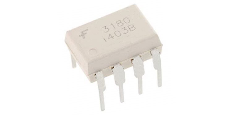
FOD3180 Introduction
This MOSFET Gate Driver Optocoupler provides a 2A output current. FOD3180 comes in two different packages with eight pins. It finds its applications in different circuits for removing noise, isolating high-frequency circuits, performing speedy DC-DC conversions, motor control, and especially in plasma display panels to drive their power MOSFETs. The tutorial is a brief guide to its pin configuration, features, specifications, example circuits, and applications.
FOD3180 Pinout
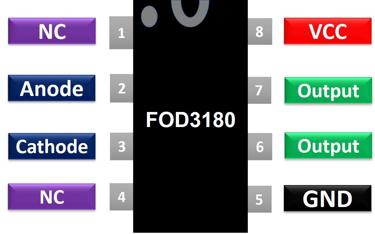
The following diagram shows the pinout of the FOD3180 Optocoupler:
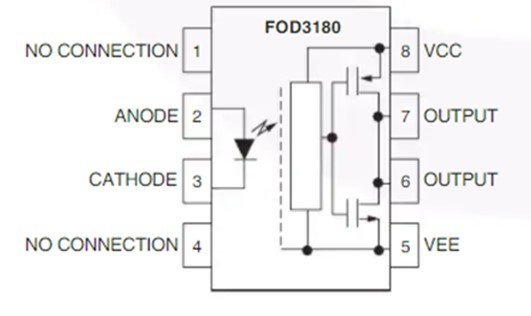
The plastic box has two sections i.e an Infrared LED which takes in the input power supply and emits light proportional to it and a CMOS detector along with PMOS and NMOS power transistors that sense this light, turn on, and starts current conduction just like a typical transistor.
Pin Configuration
Let us discuss the pinout of the FOD3180 Optocoupler. The integrated circuit consists of eight pins. The pin configuration detail in tabular is mentioned below:
| Pin Number | Pin Name | Function |
|---|---|---|
| 1 | NC | Not Connected |
| 2 | Anode | Infrared LED anode pin |
| 3 | Cathode | Infrared LED cathode pin |
| 4 | NC | Not Connected |
| 5 | VEE | Ground Reference potential pin |
| 6 | Output | Optocoupler Output pin |
| 7 | Output | Optocoupler Output pin |
| 8 | VCC | Positive Power Supply pin |
Features and Specifications
- Operating Voltage: 10 Volts – 20 Volts
- Operating Temperature: -400C to 1000C
- Average Input Current: 25 mA
- Minimum Isolation Voltage: 5000
- Rise Time: 75 ns
- Fall Time: 55 ns
- Reverse Input Voltage: 5 Volts
- High Peak Output Current: 2.5 A
- Low Peak Output Current: 2.5 A
- Peak Output Voltage: 0 – VCC
- Forward Current: 10 mA
- Reverse Current: 10 uA
- High-Speed Propagation delay: 200 nsec
- Typical Pulse Width Distortion: 30 nsec
- Maximum Switching speed: 250 kHz
- Minimum Creepage Distance: 7.0mm
- Minimum Clearance Distance: 7.0mm
- Output Power: 250 mWatts
- Total Power: 295 mWatts
- Package Type: 8-lead DIP/8-lead SMD
The optocoupler is embedded with Under Voltage Protection with hysteresis to avoid brownout. It also has a 15kV common-mode rejection to terminate common-mode signals.
Block Diagram
The block diagram of the FOD3180 MOSFET Gate Driver Optocoupler for better understanding is provided below:
FOD3180 MOSFET Gate Optocoupler Example Circuit
The figure provided below is the schematic of the FOD3180 MOSFET Gate Driver Optocoupler which takes in an AC input and provides two AC or DC outputs that are electrically isolated.
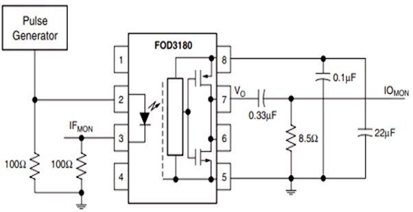
In the schematic, a Pulse generator is connected to the infrared LED along with two 100 ohms resistors. The pulse generator will produce digital rectangular signals whereas these resistors protect the IR LED and also provide control to switching of the device. The IR radiation is emitted proportional to the current. FOD3180 detects it through the embedded CMOS detector. On the output side, pin 5 and pin 8 are connected to a power supply typically 5 volts. The VCC is connected to a bypass capacitor to remove the AC noises to provide a clean output digital signal.
The output of pin 7 power MOSFET is connected to a limiting resistor to regulate and avoid the extra current. It is connected to a 0.33 uF load capacitor that represents the gate to source capacitance of a power MOSFET transistor. The FOD3180 working principle is that the CMOS detector translates the IR radiation and passes these high-frequency electric signals to the output power transistor and isolates the output and input circuitry.
FOD3180 Alternative Options
- 6N133 (equivalent)
- MOC3021
- MCT2E
- MOC3041
- 6N137
- 4N25
Applications
- High AC/DC Switching Circuits
- Signal Isolator Circuits
- Analog Current Detection
- Power Control
- Plasma Display panel
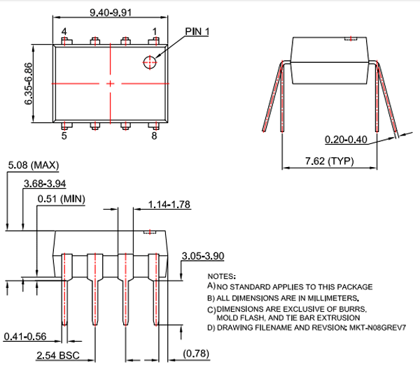
2D Diagram
Related Articles:
- EL357 Optocoupler
- SFH620A Optocoupler
- MOC3041 Zero Crossing Optocoupler
- 6N137 High Speed Optocoupler
- PC817 Optocoupler
- How to use isolated MOSFET driver TLP250
- 6N135 High Speed Optocoupler
- 4N25 Phototransistor Optocoupler
- MOC3021 Triac drive Optoisolator
- adjustable firing angle control of thyristor using arduino
- AC load interfacing with pic microcontroller