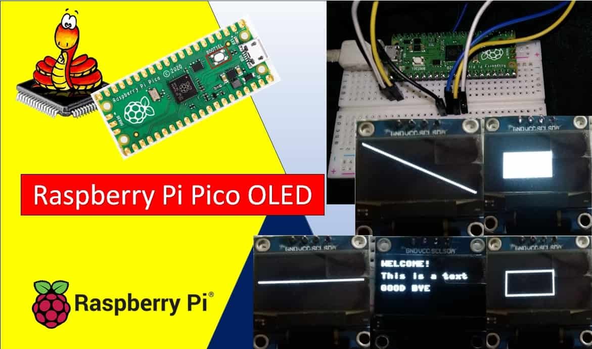
In this tutorial, we learn about the SSD1306 0.96-inch I2C OLED display and how to interface it with Raspberry Pi Pico using MicroPython. An OLED (organic light-emitting diode) is used frequently in displaying texts, bitmap images, shapes, and different types of clocks. They offer good view angles and pixel density in a cost-effective manner. At first, we will take a look at the pinout of the OLED display and then connect it with the Raspberry Pi Pico. Then we will program our board using MicroPython and then display simple messages, shapes, and graphic images on the screen.
Prerequisites
Before we start this lesson make sure you are familiar with and have the latest version Python 3 in your system, have set up MicoPython in Raspberry Pi Pico, and have a running Integrated Development Environment(IDE) in which we will be doing the programming. We will be using the same Thonny IDE as we have done previously when we learned how to blink and chase LEDs in micro-python. If you have not followed our previous tutorial, you check here:
If you are using uPyCraft IDE, you can check this getting started guide:
SSD1306 0.96inch OLED Display
Although there are several types of OLED displays available in the market the one which we will be using is the SSD1306 0.96-inch OLED display. The main component of all different types of OLED displays is an SSD1306 controller which uses I2C or SPI protocol to communicate with the microcontrollers. The OLED displays can vary in size, color, and shape but primarily programmed in a similar way.
Let us take a look at the OLED display which we will be using in this article. It is called SSD 1306 0.96-inch OLED display which has 128×64 pixels and communicates only via I2C protocol with the Pi Pico board. It is cheap and readily available in the market.
Below you can see the pinout of this OLED Display.
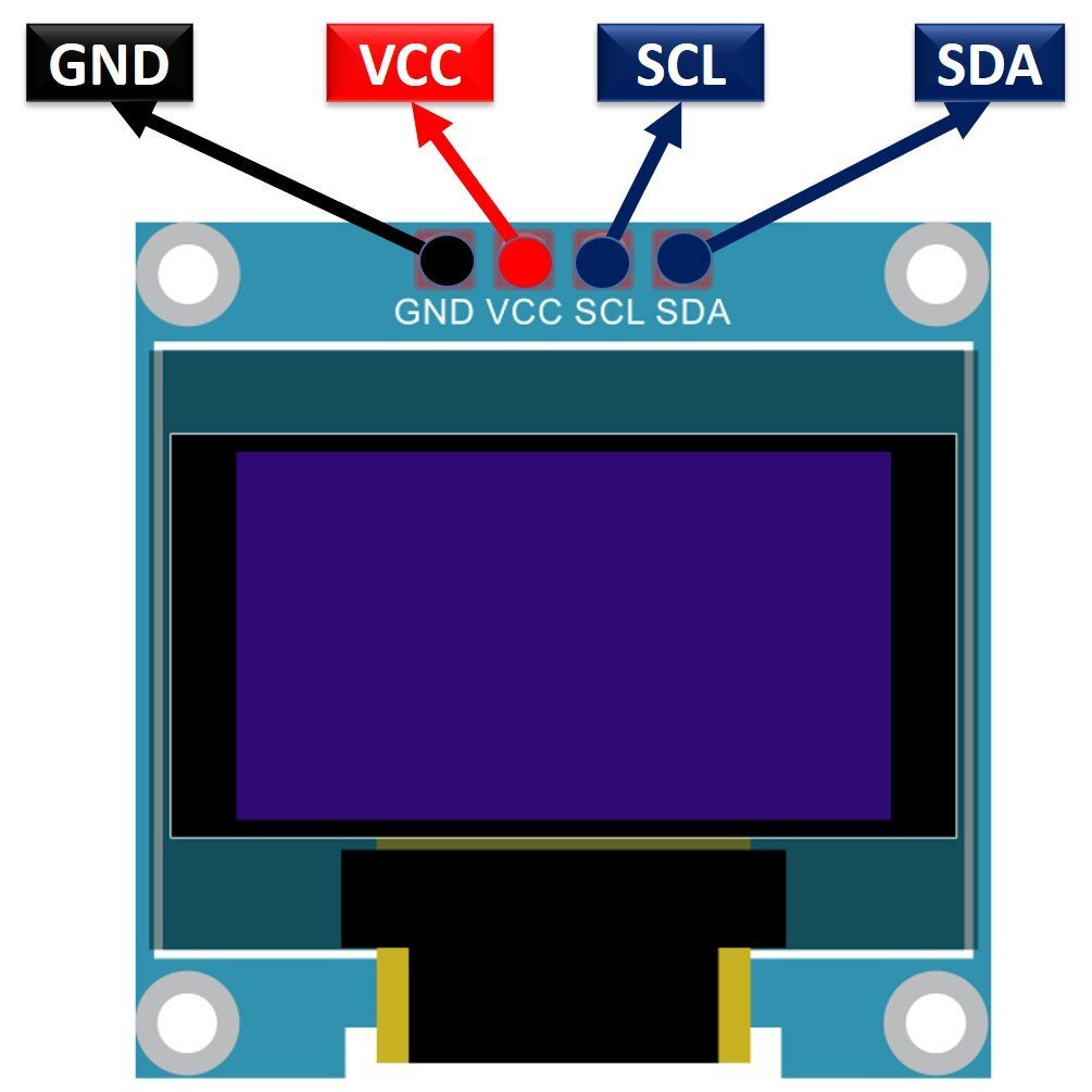
SSD1306 OLED Pinout
There are four pins in this display. Imprinted as VCC, GND, SCL, and SDA respectively. The VCC and GND pins will power the OLED display and will be connected with the Raspberry Pi Pico board’s power supply pins as they require a driving voltage of 3.3-5V. The SCL and SDA pins are necessary for generating the clock signal and in the transmission of data respectively. Both of these pins will be connected with the I2C pins of the Raspberry Pi Pico.
Now let us have a look at the specifications for this model:
| Size | 0.96 inch |
| Terminals | 4 |
| Pixels | 128×64 |
| Communication Type | I2C only |
| VCC | 3.3-5V |
| Operating Temperature | -40℃ to +80℃ |
Interfacing SSD1306 OLED Display with Raspberry Pi Pico
As we have seen above, the OLED display has 4 terminals which we will connect with the Raspberry Pi Pico. As the OLED display requires an operating voltage in the range of 3.3-5V hence we will connect the VCC terminal with 3.3V which will be in common with the board. SCL of the display will be connected with the SCL pin of the module and the SDA of the display will be connected with the SDA of the module. The ground of both the devices will be held common.
Raspberry Pi Pico I2C Pins
Raspberry Pi Pico has two I2C controllers. Both I2C controllers are accessible through GPIO pins of Raspberry Pi Pico. The following table shows the connection of GPIO pins with both I2C controllers. Each connection of the controller can be configured through multiple GPIO pins as shown in the figure. But before using an I2C controller, you should configure in software which GPIO pins you want to use with a specific I2C controller.
| I2C Controller | GPIO Pins |
| I2C0 – SDA | GP0/GP4/GP8/GP12/GP16/GP20 |
| I2C0 – SCL | GP1/GP5/GP9/GP13/GP17/GP21 |
| I2C1 – SDA | GP2/GP6/GP10/GP14/GP18/GP26 |
| I2C1 – SCL | GP3/GP7/GP11/GP15/GP19/GP27 |
The connections between the two devices which we are using can be seen below.
| SSD1306 OLED Display | Raspberry Pi Pico |
| VCC | 3.3V |
| SDA | GP0 (I2C0 SDA) |
| SCL | GP1 (I2C0 SCL) |
| GND | GND |
Components Required
We will need the following components to connect our Raspberry Pi Pico with the OLED Display.
- Raspberry Pi Pico
- SSD1306 OLED Display
- Connecting Wires
Schematic Raspberry Pi Pico with OLED
Follow the schematic diagram below connect them accordingly.
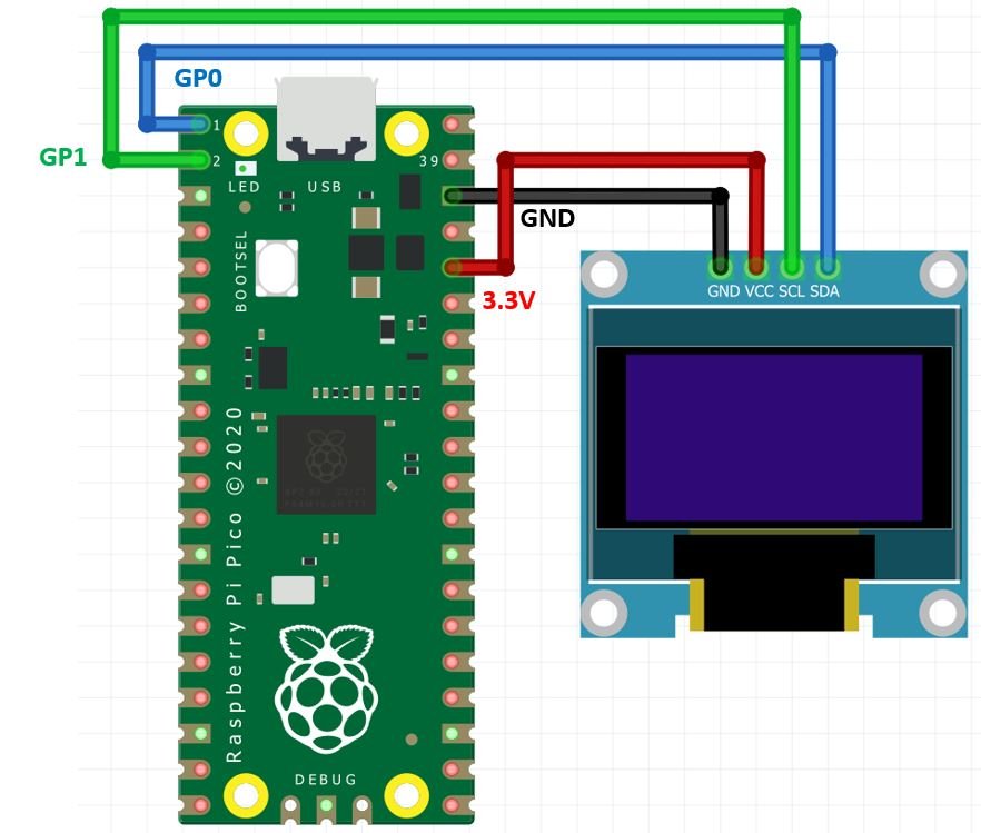
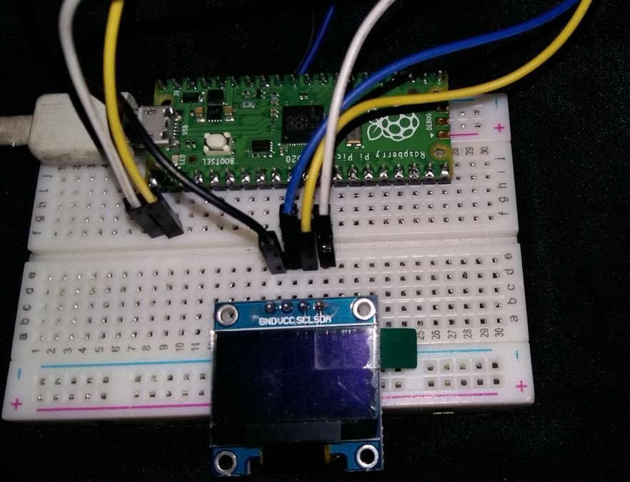
We have used the same connections as specified in the table above. However you can use other combinations of SDA/SCL pins as well.
SSD1306 OLED MicroPython Library
We will have to install the SSD1306 OLED library for MicroPython to continue with our project.
- To successfully do that, open your Thonny IDE with your Raspberry Pi Pico plugged in your system. Go to Tools > Manage Packages. This will open up the Thonny Package Manager.
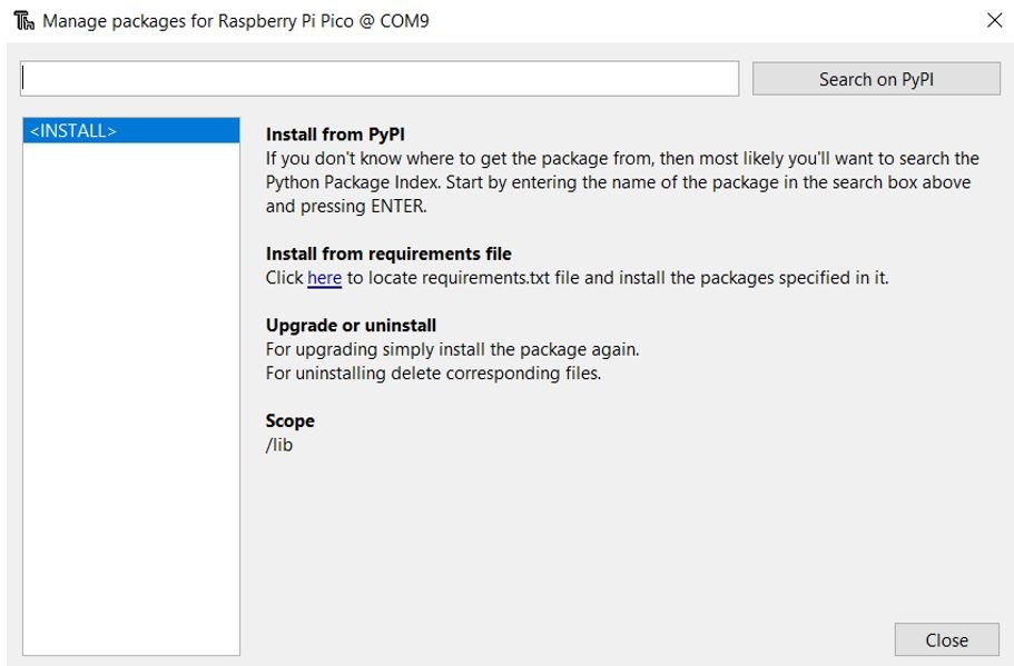
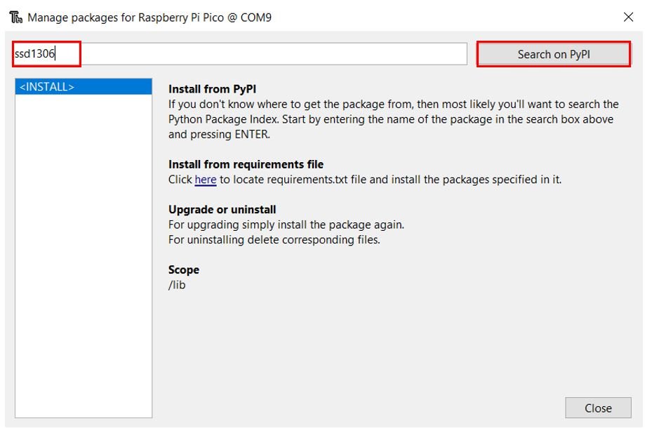
- Search for “ssd1306” in the search bar by typing its name and clicking the button ‘Search on PyPI.’
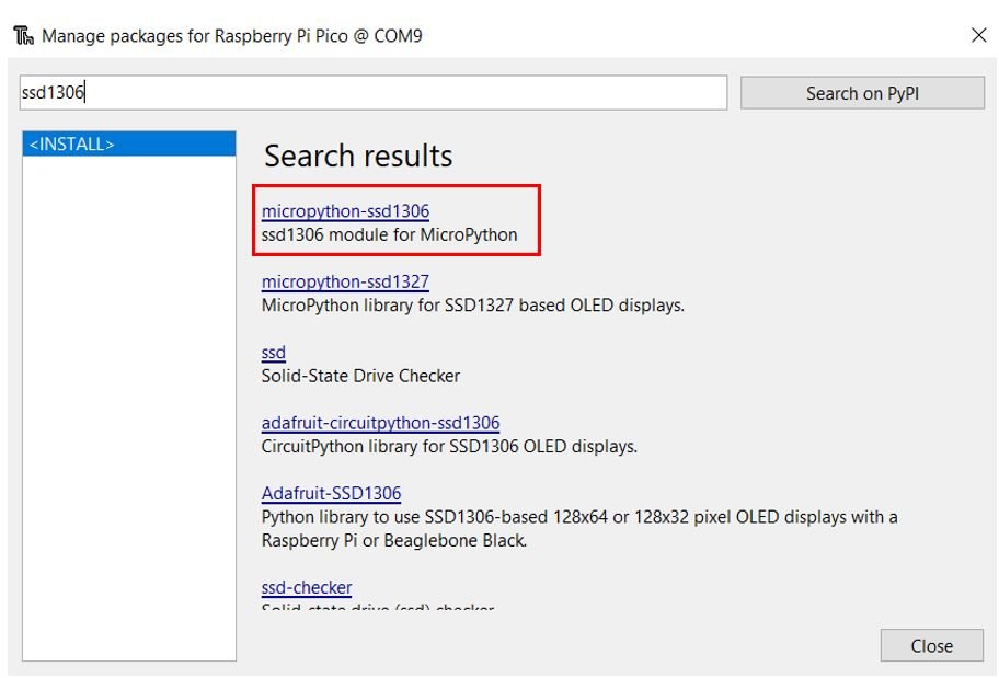
- From the following search results click on the one highlighted below: micropython-ssd1306
Install this library.
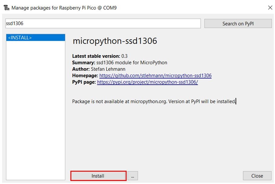
After a few moments this library will get successfully installed. Now we are ready to program our Raspberry Pi Pico with OLED display.
Raspberry Pi Pico MicroPython Script: Displaying simple messages on OLED Display
This code will display three messages on the OLED display.
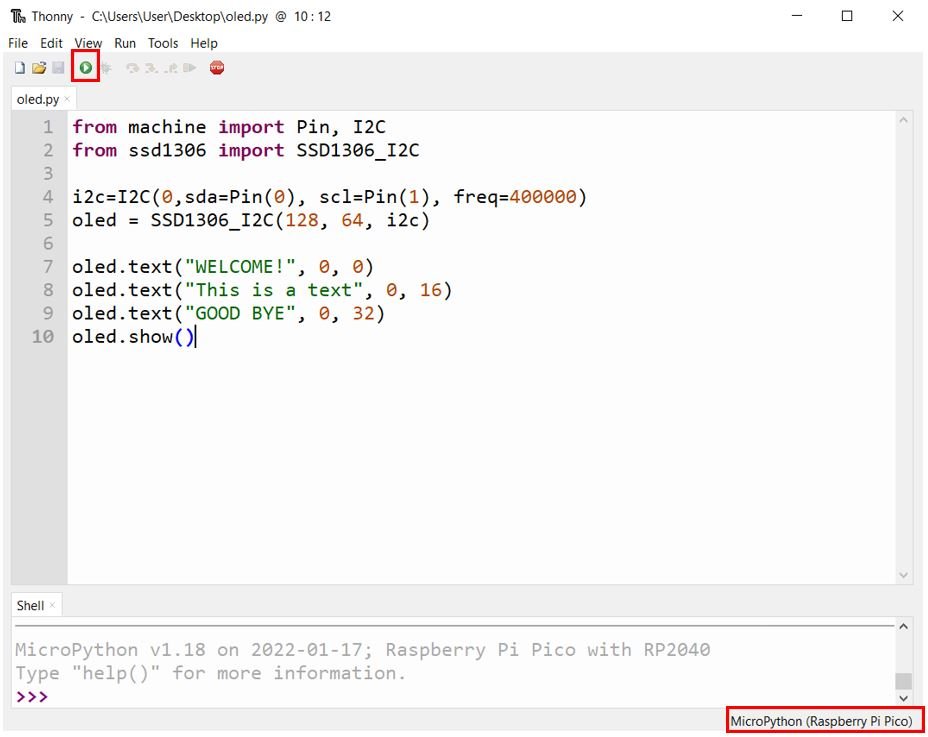
Open a new file and save the file as oled.py. Copy the code given below in that file.
from machine import Pin, I2C
from ssd1306 import SSD1306_I2C

i2c=I2C(0,sda=Pin(0), scl=Pin(1), freq=400000)
oled = SSD1306_I2C(128, 64, i2c)

oled.text("WELCOME!", 0, 0)
oled.text("This is a text", 0, 16)
oled.text("GOOD BYE", 0, 32)
oled.show()
How the Code works?
Importing I2C and OLED Library
We start off by importing the pin and the I2C classes from the machine module. Because we have to interact with the GPIO pins and transmit data through the I2C protocol hence both these classes are necessary. We will also import the ssd1306 which is the OLED display library that we installed earlier. This will help us in accessing all the functions defined inside it.
from machine import Pin, I2C
from ssd1306 import SSD1306_I2C
Selecting I2C Pins for OLED
Next, we will initialize the I2C GPIO pins for SCL and SDA respectively. We have used the I2C0 SCL and I2C0 SDA pins.
We have created an I2C() method which takes in four parameters. The first parameter is the I2C channel that we are using. The second parameter specifies the I2C GPIO pin of the board which is connected to the SDA line. The third parameter specifies the I2C GPIO pin of the board which is connected to the SCL line. The last parameter is the frequency connection of the OLED.
We are setting the SCL on pin 1 and the SDA on pin 0.
i2c=I2C(0,sda=Pin(0), scl=Pin(1), freq=400000)Initialize OLED
This SCL and SDA pin data gets saved in the object ‘i2c’ which will connect to the I2C bus and help in the communication between the two devices
Now, we will create an object ‘oled’ of SSD1306_I2C which uses the width, height, and the i2c object as parameters.
oled = SSD1306_I2C(128, 64, i2c)Displaying Text on OLED
Next, we used the text() function on the oled object which we initialized before. The text() function takes in three arguments.
- First argument to text() is the text which we want to display. This should be in the form of ‘string.’ We will be displaying three different texts.
- The second argument is the horizontal position where the text starts. This is known as the ‘X position.’ We will specify it as 0.
- The third argument is the ‘Y position’ which is the vertical position from where the text starts. We will specify it first as 0, then 16, and lastly as 32 to view the three messages which we will display in three rows, one after another. The horizontal position remains the same in all.
- The fourth argument is the colour of the text. We are not specifying any fourth argument so it will be set as default which is white. You can choose between black and white. For white, we specify 1 and for black, we specify 0.
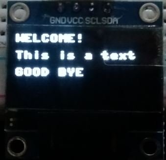
To display text just use the text() function on the oled object. The following code displays the message: ‘Welcome to Lab’ on x=0 and y=0. ‘This is a text’ on x=0 and y=16 and ‘GOOD BYE’ on x=0 and y=32.
oled.text("WELCOME!", 0, 0)
oled.text("This is a text", 0, 16)
oled.text("GOOD BYE", 0, 32)
Lastly, we will use the show() method on the oled object to successfully display the messages on the OLED Display.
oled.show()Demonstration
After you have copied the following code onto the file click on ‘Save’ icon to save your program code on your PC. Save your file by giving it a name oled.py and save according to your preference by giving the directory.
After you have saved the code press the Run button to upload the code to your Raspberry Pi Pico module. Before uploading code make sure the correct board is selected.
The OLED will display the messages as shown below:
Draw Pixels, Lines and Shapes on OLED with Raspberry Pi Pico
Now let us move ahead and learn how to display pixels, lines, and shapes on the OLED display. By the end of this section you will be able to display the following on your OLED screen:
- Pixel
- Horizontal Line, Vertical Line and Diagonal Line
- Rectangle (Unfilled and Filled)
MicroPython Script
This sketch will display all the above listed illustrations after a delay of 2 seconds.
from machine import Pin, I2C
from ssd1306 import SSD1306_I2C
from time import sleep

i2c=I2C(0,sda=Pin(0), scl=Pin(1), freq=400000)
oled = SSD1306_I2C(128, 64, i2c)

while True:
      oled.pixel(64,32,1)
      oled.show()
      sleep(2)
      oled.fill(0)

      oled.hline(0,32,128,1)
      oled.show()
      sleep(2)
      oled.fill(0)

      oled.vline(0, 0, 64, 1)
      oled.show()
      sleep(2)
      oled.fill(0)

      oled.line(0, 0, 128, 64, 1)
      oled.show()
      sleep(2)
      oled.fill(0)

      oled.rect(20, 20, 64, 32, 1)
      oled.show()
      sleep(2)
      oled.fill(0)

      oled.fill_rect(20, 20, 64, 32, 1)
      oled.show()
      sleep(2)
      oled.fill(0)
In this part, we will show you how to display the different illustrations. We will include the code to display the pixels, lines, and different shapes. Each illustration will display on the OLED screen for 2 seconds and then the next one follows.
Before displaying each shape we will call the fill(0) function to clear the buffer for the next illustration.
Displaying a Pixel
Firstly, we will display a pixel on the OLED screen. This is achieved by using the pixel() function on the oled object. This function takes in three parameters. The first parameter is the x coordinate, the second parameter is the y coordinate and the third parameter is the colour of the pixel. We have passed (64,32) as the (x, y) coordinates of the pixel that denotes the centre of the screen. The third parameter denotes the colour which is set as white. For white, we specify 1 and for black, we specify 0.
Additionally, we will call the show() function on the display object so that the pixel displays on the OLED.
oled.pixel(64,32,1)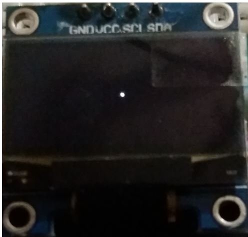
Draw Line
Secondly, we will display three types of lines on the OLED screen. Horizontal, Vertical and Diagonal Lines.
      oled.hline(0,32,128,1)
      oled.show()
      sleep(2)
      oled.fill(0)

      oled.vline(0, 0, 64, 1)
      oled.show()
      sleep(2)
      oled.fill(0)

      oled.line(0, 0, 128, 64, 1)
      oled.show()
      sleep(2)
      oled.fill(0)
The first one is the horizontal line. This is achieved by using the hline() function on the oled object. This function takes in four parameters. The first two parameters are x,y coordinates till the horizontal line is drawn. The third parameter is the width in pixels. The last argument is the colour.
oled.hline(0,32,128,1)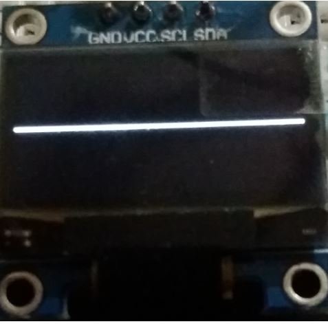
Next we will display a vertical line. This is achieved by using the vline() function on the oled object. This function takes in four parameters. The first two parameters are x,y coordinates from which the vertical line is drawn. The third parameter is the height in pixels. The last argument is the colour.
oled.vline(0, 0, 64, 1)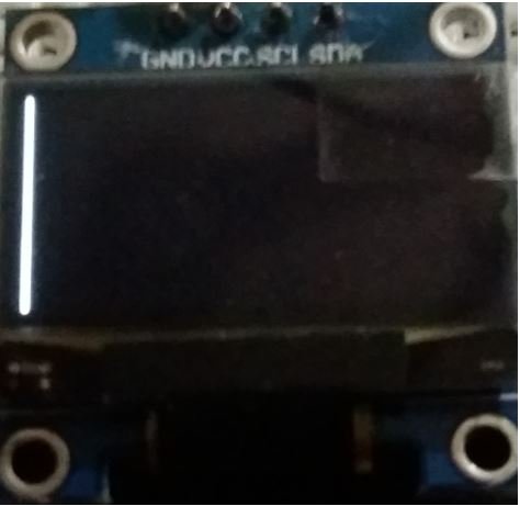
Lastly, we will display a diagonal line. The first two parameters are the starting (x1, y1) coordinates and the next two parameters are the ending (x2, y2) coordinates of the line. Lastly the fifth parameter is the colour of the line. We have passed (0,0) as the starting coordinates and (128, 64) as the ending coordinates of the line. It will be white in colour.
Additionally, we will call the show() function on the oled object so that the line displays on the OLED.
oled.line(0, 0, 128, 64, 1)
Draw Rectangle (Unfilled and Filled)
Next, we will display unfilled and filled rectangles on the OLED screen.
      oled.rect(20, 20, 64, 32, 1)
      oled.show()
      sleep(2)
      oled.fill(0)

      oled.fill_rect(20, 20, 64, 32, 1)
      oled.show()
      sleep(2)
      oled.fill(0)
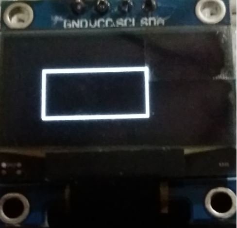
First, we will display an unfilled rectangle. This is achieved by using the rect() function on the oled object. This function takes in five parameters. The first two parameters are the starting (x1, y1) coordinates. The next two parameters are the width and height of the rectangle. Lastly the fifth parameter is the colour of the rectangle. We have passed (20,20) as the starting coordinates and 64 as the width and 32 as the height of the rectangle. It will be white in colour. Additionally, we will call the show() function on the oled object so that the rectangle displays on the OLED.
oled.rect(20, 20, 64, 32, 1)
Next, we will display a filled rectangle. This is achieved by using the fill_rect() function on the oled object. This function takes in five parameters. The first two parameters are the starting (x1, y1) coordinates. The next two parameters are the width and height of the rectangle. Lastly the fifth parameter is the colour of the rectangle. We have passed (20,20) as the starting coordinates and 64 as the width and 32 as the height of the rectangle. It will be white in colour. Additionally, we will call the display() function on the oled object so that the rectangle displays on the OLED.
oled.fill_rect(20, 20, 64, 32, 1)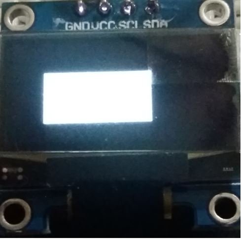
Demonstration
After you have copied the following code onto the file click on ‘Save’ icon to save your program code on your PC.
After you have saved the code press the Run button to upload the code to your Raspberry Pi Pico module. Before uploading code make sure the correct board is selected.
Once the code is uploaded to Raspberry Pi Pico, you will be able to view all the above mentioned figures on the OLED display after a gap of 2 seconds. Watch the video below to have a look.
You may like to read:
- Raspberry Pi Pico GPIO Programming with MicroPython – LED Blinking Examples
- Interface Push Button with Raspberry Pi Pico and Control LED
- Raspberry Pi Pico ADC with Voltage Measurement Examples
- PIR Motion Sensor with Raspberry Pi Pico using External Interrupts
- Raspberry Pi Pico PWM MicroPython LED Fading Examples
- Generate Delay with Raspberry Pi Pico Timers using MicroPython
If a person tries to download the ssd1306 from PyPi they will get an error and the error is invalid certificate. I had to go to github and create thessd1306 from the raw code and also the supporting files needed for ssd1306 to work.
I didn’t have any problems. The library installed fine. I am on latest Windows 10 with Thonny 4.0.1
How would one display on the OLED the time from a DS3231 real time clock ?
Thanks
Excellent, all worked first time. Very helpful, thank you.
OMG, so easy and simple;
Best Guide EVER!
Worked perfectly for me – a first!