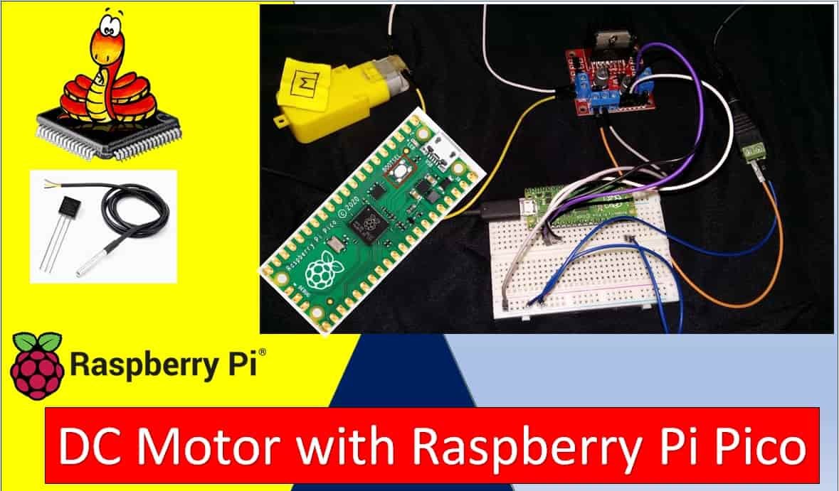
In this guide, we will learn how to control a DC motor with Raspberry Pi Pico using MicroPython and an L298N motor driver module. We will introduce you to the L298N motor driver module, explain how it works internally, and then use it to demonstrate basic DC motor control including start, stop, forward, and backward motion through the Raspberry Pi Pico board.
We have similar guides for ESP32, ESP8266, and Arduino using Arduino IDE:
- Interface L298N DC Motor Driver Module with ESP32
- Interfacing L298N DC Motor Driver Module with ESP8266 NodeMCU
- Interface L298N DC Motor Driver Module with Arduino
- MicroPython: Control a DC Motor using L298N Driver with ESP32 and ESP8266
Prerequisites
Before starting this lesson, make sure you have the latest version of Python 3 installed on your system and MicroPython set up on your Raspberry Pi Pico. You should also have a working Integrated Development Environment (IDE) for programming. We will be using Thonny IDE throughout this tutorial:
If you are using uPyCraft IDE, you can check this getting started guide:
L298N Motor Driver Module
DC motors cannot be driven directly from a microcontroller because they require higher current and voltage than what GPIO pins can supply. Motor driver ICs like the L298N act as a bridge between the microcontroller and the motor, amplifying the control signals to safely drive the motor. The L298N module is one of the most popular and affordable motor driver solutions available for hobbyist and educational robotics projects.
The L298N module can control up to two DC motors simultaneously with full speed and direction control. This makes it ideal for two-wheeled differential drive robots, conveyor systems, and any application requiring bidirectional motor control. The module is also compatible with stepper motors, making it a versatile component to have in your electronics toolkit.
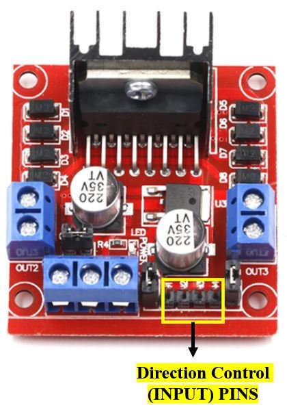
The L298N motor driver module consists of an L298N motor driver IC, a 78M05 5V voltage regulator, a 5V jumper enable, a power LED indicator, a heat sink, resistors, and capacitors, all integrated onto a single PCB. The diagram below shows all the components inside the module.
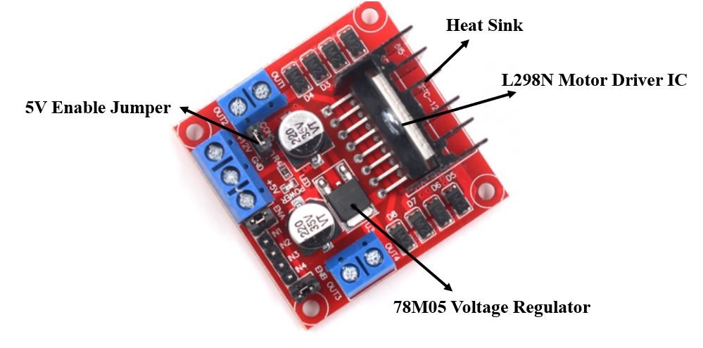
The L298N motor driver IC features a large heat sink to dissipate heat during high-current operation. It implements a dual H-bridge topology that can drive two independent motors. The H-bridge design allows current to flow in either direction through the motor windings, enabling forward and reverse rotation without any additional circuitry.
The onboard 78M05 voltage regulator provides a stable 5V supply enabled through a jumper. When the jumper is intact and the motor supply voltage is below 12V, the regulator powers the 5V pin as an output, which can be used to power the microcontroller. If your motor supply voltage exceeds 12V, remove the jumper and supply 5V separately to the 5V pin.
Note: When the jumper is connected, do not supply power to both the motor power supply input and the 5V power supply input simultaneously, as this can damage the onboard regulator.
How the H-Bridge Works
Understanding the H-bridge circuit is key to understanding how the L298N controls DC motors. An H-bridge consists of four switching elements (transistors or MOSFETs) arranged in an “H” shape around the motor. By closing different pairs of switches, current can be forced to flow through the motor in either direction, which determines the motor’s rotation direction.
When switches on the top-left and bottom-right are closed, current flows from left to right through the motor, spinning it in one direction. When switches on the top-right and bottom-left are closed, current flows in the opposite direction, reversing the motor. Opening all switches stops the motor. The L298N contains two complete H-bridge circuits, one for each motor channel (A and B).
One important characteristic of the L298N is that it uses bipolar transistors internally, which introduce a voltage drop of approximately 2V across the H-bridge. This means a motor powered at 9V from the supply will actually receive around 7V at its terminals. For most hobbyist applications this is acceptable, but it is worth keeping in mind when selecting your power supply voltage.
Specifications
The table below shows the key specifications of the L298N motor driver module:
| Driver Model | L298N |
| Driver Chip | Double H-bridge L298N |
| Maximum Power | 25W |
| Maximum Motor Supply Voltage | 46V |
| Maximum Motor Supply Current | 2A per channel |
| Driver Voltage Range | 5–35V |
| Logic Input Voltage | 3.3V – 5V (TTL compatible) |
| Onboard Voltage Regulator | 78M05 (5V output, max 36V input) |
| Internal Voltage Drop | ~2V across H-bridge |
| Size | 43 x 43 x 26 mm |
Pinout
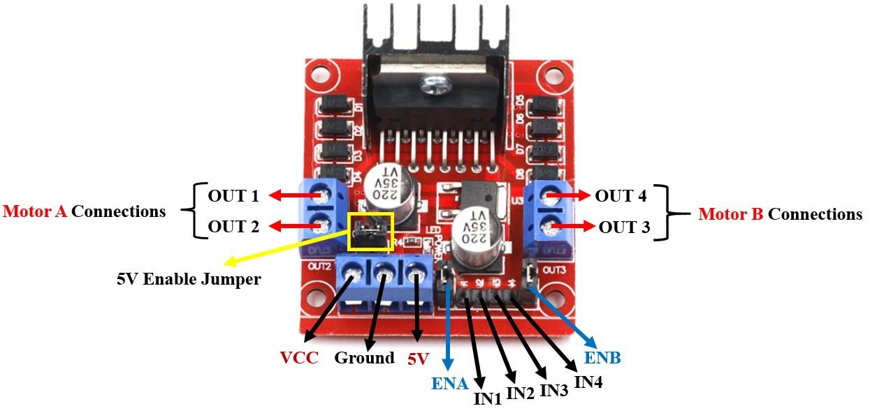
Let us now look at the pinout of the L298N module:
| Pin Name | Description |
| VCC | Motor power supply pin. Labeled +12V on the board but supports 6–35V. Connect your external motor power supply here. |
| GND | Common ground pin. Connect both the motor power supply ground and the microcontroller ground here. |
| 5V | Logic power supply for the L298N IC. When the 5V jumper is intact, this pin acts as an output (powered by the onboard 78M05 regulator). Remove the jumper if the motor supply exceeds 12V and provide 5V externally through this pin. |
| ENA | Enable pin for Motor A. Controls motor speed via PWM when connected to a PWM-capable GPIO pin. A jumper keeps this HIGH by default for full speed operation. |
| IN1 & IN2 | Direction control inputs for Motor A. Setting them to opposite logic levels spins the motor. Same level stops it. |
| IN3 & IN4 | Direction control inputs for Motor B. Operates the same way as IN1 & IN2 for Motor B. |
| ENB | Enable pin for Motor B. Works the same way as ENA for Motor B speed control. |
| OUT1 & OUT2 | Motor A output terminals. Connect your DC motor’s two wires here. Swapping these wires will reverse the default rotation direction. |
| OUT3 & OUT4 | Motor B output terminals. Connect the second motor here for dual-motor control. |
Controlling DC Motors through the L298N Module
Motor control with the L298N involves two separate aspects: speed control through PWM on the enable pins, and direction control through logic signals on the input pins. Understanding both is essential for smooth, predictable motor operation.
Control Pins
There are two types of control pins on the module. The enable pins (ENA and ENB) control speed, while the input pins (IN1–IN4) control direction. Both sets must be configured correctly for the motor to operate as expected.
Speed Control (ENABLE) Pins
The ENA and ENB pins enable and disable each motor channel and also control motor speed through PWM (Pulse Width Modulation). When these pins receive a PWM signal, the motor speed is proportional to the duty cycle: a higher duty cycle results in faster motor rotation.
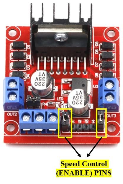
ENA controls the speed of Motor A and ENB controls Motor B. When either pin is driven HIGH (logic 1), the corresponding motor is enabled and runs at full speed. When driven LOW (logic 0), the motor stops. By applying a PWM signal instead of a steady HIGH or LOW, you can smoothly vary the motor speed anywhere between stopped and full speed.
On the Raspberry Pi Pico, PWM duty cycle values range from 0 to 65535 using the duty_u16() method. A value of 0 means the motor is fully stopped, while 65535 means full speed. For example, a duty cycle value of 32768 represents approximately 50% speed. The PWM frequency is typically set to 1000 Hz (1 kHz), which provides smooth motor operation without audible noise from the motor windings.
| ENA Pin State | Motor Action |
| HIGH (logic 1) | Motor enabled (full speed) |
| LOW (logic 0) | Motor disabled (stopped) |
| PWM signal | Motor runs at proportional speed |
Direction Control (INPUT) Pins
The four input pins IN1, IN2, IN3, and IN4 determine the rotation direction of each motor. IN1 and IN2 control Motor A, while IN3 and IN4 control Motor B. The logic level applied to these pins switches the H-bridge transistors to route current through the motor in the desired direction.
The following truth table shows the logic signals required for Motor A control. Motor B operates identically using IN3 and IN4:
| IN1 | IN2 | Motor Action |
| HIGH (1) | HIGH (1) | Stop (brake) |
| HIGH (1) | LOW (0) | Backward (reverse) |
| LOW (0) | HIGH (1) | Forward |
| LOW (0) | LOW (0) | Stop (coast) |
When IN1 and IN2 are set to different logic levels, the motor spins. When both are the same (both HIGH or both LOW), the motor stops. The difference between both-HIGH (brake) and both-LOW (coast) is subtle: in brake mode, the motor windings are shorted together creating an active braking effect, while in coast mode the motor is simply disconnected and decelerates gradually under its own inertia.
Interfacing DC Motor and L298N Motor Driver with Raspberry Pi Pico
Now that we understand how to control the DC motor through the motor driver, let us build the actual circuit with our Raspberry Pi Pico board.
Required Components
- Raspberry Pi Pico
- L298N Motor Driver Module
- Mini DC Motor (6–12V rated)
- 9V battery or external power supply
- 0.1µF ceramic capacitor (optional, for noise suppression)
- Slide switch (optional, for convenient power control)
- Breadboard and connecting wires
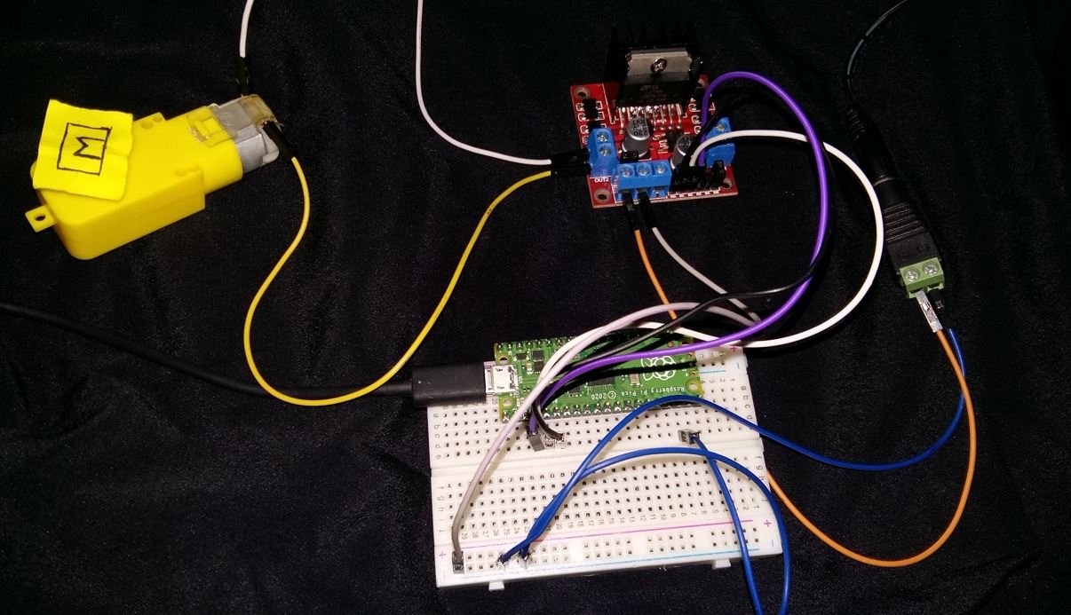
Assemble the circuit as shown in the connection diagram below.

We are using Motor A’s output pins to control the DC motor. GP4 connects to ENA for speed control via PWM, while GP3 connects to IN1 and GP2 connects to IN2 for direction control. You can use other GPIO pins on the Pico as needed, as long as you use a PWM-capable pin for ENA.
The DC motor is rated at 6–12V and draws significant startup current, which is why an external power source is required. We use a 9V battery connected through an optional slide switch so we can conveniently cut power without disconnecting wires. The 0.1µF ceramic capacitor is soldered or placed directly across the motor’s two terminals to suppress voltage spikes generated when the motor’s brushes commutate. These voltage spikes can interfere with the microcontroller if left unchecked, so the capacitor is strongly recommended even though it is technically optional.
Make sure to connect the grounds of the Raspberry Pi Pico and the external motor power supply together at the L298N GND pin. A common ground reference is essential for the logic signals from the Pico to correctly control the L298N driver.
MicroPython Script: Control DC Motor
Copy the following code and save it as main.py on your Raspberry Pi Pico board. The motor will cycle through forward motion, a brief stop, then backward motion at progressively increasing speeds, repeating indefinitely.
from machine import Pin, PWM
from time import sleep

IN1 = Pin(3, Pin.OUT)
IN2 = Pin(2, Pin.OUT)

speed = PWM(Pin(4))
speed.freq(1000)

while True:
        speed.duty_u16(10000)
        IN1.low()  # spin forward
        IN2.high()
        sleep(5)

        IN1.low()  # stop (coast)
        IN2.low()
        sleep(2)

        speed.duty_u16(20000)
        IN1.high()  # spin backward
        IN2.low()
        sleep(5)

        IN1.low()  # stop (coast)
        IN2.low()
        sleep(2)

        speed.duty_u16(30000)
        IN1.low()  # spin forward
        IN2.high()
        sleep(5)

        IN1.low()  # stop (coast)
        IN2.low()
        sleep(2)

        speed.duty_u16(40000)
        IN1.high()  # spin backward
        IN2.low()
        sleep(5)
How the Code Works
We begin by importing the Pin and PWM classes from the machine module, along with sleep from the time module. The machine module provides low-level hardware access to the Pico’s GPIO pins, and sleep creates time delays between each motor operation phase.
from machine import Pin, PWM
from time import sleep
Next, we configure GP3 and GP2 as digital output pins. These are connected to the IN1 and IN2 direction control inputs of the L298N. The Pin.OUT argument sets the pin mode to digital output so we can drive it HIGH or LOW to control motor direction.
IN1 = Pin(3, Pin.OUT)
IN2 = Pin(2, Pin.OUT)
We then create a PWM object on GP4 and set its frequency to 1000 Hz (1 kHz). The 1 kHz frequency is a common choice for DC motor speed control as it provides smooth operation. Frequencies that are too low can cause audible buzzing from the motor, while very high frequencies may not be as effectively filtered by the motor’s inductive characteristics.
speed = PWM(Pin(4))
speed.freq(1000)
Changing Speed and Direction
Inside the infinite while True loop, the motor cycles through different speed and direction combinations. The duty cycle is set using speed.duty_u16(), which accepts values from 0 (motor off) to 65535 (full speed). To put these numbers in perspective: 10000 is approximately 15% speed, 20000 is about 30%, 30000 is about 46%, and 40000 is about 61% of maximum speed.
For forward motion, IN1 is set LOW and IN2 is set HIGH. This forward state is maintained for 5 seconds before stopping:
speed.duty_u16(10000)
IN1.low()  # spin forward
IN2.high()
sleep(5)
Stopping the motor is done by setting both IN1 and IN2 to LOW, which puts the H-bridge in coast mode. The motor decelerates gradually due to its rotational inertia:
IN1.low()  # stop (coast)
IN2.low()
sleep(2)
For backward (reverse) motion, IN1 is set HIGH and IN2 is set LOW. Notice that the duty cycle is increased to 20000 for this backward phase, making the motor run faster than in the previous forward phase:
speed.duty_u16(20000)
IN1.high()  # spin backward
IN2.low()
sleep(5)
This pattern repeats with increasing duty cycle values (30000 and 40000) so you can observe the effect of increasing PWM duty cycle on motor speed. You can modify these duty cycle values to match your specific motor and application requirements.
Troubleshooting
If you encounter issues with your DC motor and L298N setup, the following common problems and solutions should help you diagnose and fix them.
Motor does not spin at all: First verify that the external power supply is connected and switched on. Check that the ground of the Pico and the ground of the motor power supply are both connected to the L298N GND pin. If the ENA jumper is missing, the motor channel is disabled by default, so either replace the jumper or connect a HIGH signal to ENA from the Pico. Also confirm that IN1 and IN2 are receiving the correct logic signals using a multimeter or by printing the pin values to the shell.
Motor spins in the wrong direction: Simply swap the two motor wires connected to OUT1 and OUT2, or invert the logic in your code by swapping the HIGH and LOW assignments for IN1 and IN2.
Motor runs but speed control does not work: Make sure the ENA jumper has been removed. The jumper holds ENA permanently HIGH, which prevents the PWM signal from taking effect. Once the jumper is removed and GP4 is connected to ENA, the duty_u16() values will control the motor speed as expected.
L298N module overheating: This typically happens when the motor draws more than the rated 2A per channel, or when the ambient temperature is high. Ensure your motor’s stall current does not exceed 2A. You can also add a small heatsink compound to the L298N IC body or improve airflow around the board. Avoid running the motor at full load for extended periods without a heatsink.
Motor runs erratically or the Pico resets unexpectedly: This is usually caused by electrical noise from the motor’s brushes feeding back into the power supply. Make sure the 0.1µF capacitor is placed directly across the motor terminals. Additionally, ensure the motor power supply is separate from the Pico’s power supply (do not power the Pico through a 5V source shared with the motor).
Motor speed is lower than expected: Remember that the L298N has an internal voltage drop of approximately 2V. A 9V supply will deliver roughly 7V to the motor. If you need higher speed, increase your supply voltage accordingly (within the motor’s rated range), or consider a MOSFET-based driver like the TB6612FNG which has a much lower voltage drop.
Demo
To test the MicroPython script for DC motor control with Raspberry Pi Pico, save the code as main.py and upload it to your board using Thonny IDE. Press the Run button or reset the Pico to start execution.
Video Demo:
You may like to read servo and stepper motor interfacing with Raspberry Pi Pico:
- 28BYJ-48 Stepper Motor with Raspberry Pi Pico using MicroPython
- Servo Motor with Raspberry Pi Pico using MicroPython
You may also like to read:
- DS18B20 Temperature Sensor with Raspberry Pi Pico using MicroPython
- DHT11 DHT22 with Raspberry Pi Pico using MicroPython
- HC-SR04 Ultrasonic Sensor with Raspberry Pi Pico using MicroPython
- I2C LCD Interfacing with Raspberry Pi Pico Display Text and Custom Characters
- MPU6050 with Raspberry Pi Pico (Accelerometer, Gyroscope, and Temperature)
- BME280 with Raspberry Pi Pico using MicroPython
- OLED Display with Raspberry Pi Pico using MicroPython
Great training / learning material. Please keep the awsome work.
Dear sir/madam,
I’ve an actuator (motor) which needs a power voltage of 24V.
In the spec’s I read the L298N can supply a motor Voltage up to 46V.
My question:
Is a 12V external power supply for the L298N enough?
Or should I connect an external 24V power supply?
I did think I should connect a 24V power supply for the 24V motor.
But that’s a contradiction with the 12V power supply which is described in your manual.
Can you please help me and tell me do I need to connect a 12V or 24V power supply for a 24V actuator (motor) with this L298N module?
Thanks in advance for your answer