In this tutorial, we will learn about a NEO-6M GPS module and how to interface it with ESP32 using MicroPython to obtain GPS parameters such as latitude, longitude, altitude, date, time, speed, satellites, etc. We will learn how GPS works and the overview of the NEO-6M GPS module with an introduction, pinout, and specifications. After that, we will learn to interface a NEO-6M GPS Module module with ESP32.
Recommended Components
The following components are used in this project or are helpful for getting started with MicroPython on ESP32 and ESP8266.
| Component | How it’s used in this project | Buy on Amazon |
|---|---|---|
| ESP32 Development Board (DevKit V1) | The ESP32 board flashed with MicroPython firmware. | Check Price |
| Micro USB Cable | Programs and powers the board from your PC. | Check Price |
| NEO-6M GPS Module | Receives satellite data for latitude, longitude, and time. | Check Price |
| Breadboard | Holds the components for prototyping the circuit. | Check Price |
| Jumper Wires | Connects the GPS module and OLED to the ESP32. | Check Price |
As an Amazon Associate we earn from qualifying purchases. Prices and availability are accurate as of the date/time indicated and are subject to change.
For demonstration purposes, we will display the GPS location parameters including latitude, longitude, number of satellites, and current time on the Thonny shell console as well as on an OLED.
We have a similar guide with Raspberry Pi Pico:
Prerequisites
Before we start this lesson make sure you are familiar with and have the latest version of MicroPython firmware installed in your ESP32 board and have a running Integrated Development Environment (IDE) in which we will be doing the programming such as uPyCraft IDE or Thonny IDE.
- Getting Started with uPyCraft IDE on ESP32 and ESP8266
- Getting Started with Thonny MicroPython IDE for ESP32 and ESP8266
If you want to use VS Code, you can follow this guide:
- MicroPython ESP32 and ESP8266: Program with VS Code and Pymakr
- Flash MicroPython Firmware with esptool.py to ESP32 and ESP8266
GPS Introduction
Recommended Reading: GPS ( Global Positioning System) – working
The Global Positioning System (GPS) is a satellite-based navigation system that consists of 24 orbiting satellites, each of which makes two circuits around the Earth every 24 hours. These satellites transmit three bits of information – the satellite’s number, its position in space, and the time the information is sent. These signals are picked up by the GPS receiver, which uses this information to calculate the distance between it and the GPS satellites. With signals from three or more satellites, a GPS receiver can triangulate its location on the ground (i.e., longitude and latitude) from the known position of the satellites. With four or more satellites, a GPS receiver can determine a 3D position (i.e., latitude, longitude, and elevation).
In addition, a GPS receiver can provide data on your speed and direction of travel. Anyone with a GPS receiver can access the system. Because GPS provides real-time, three-dimensional positioning, navigation, and timing 24 hours a day, 7 days a week, all over the world, it is used in numerous applications, including GIS data collection, surveying, and mapping.
Point to Remember: A GPS receiver locates any three or more of the satellites, calculates the distande to each, and uses this information to generate its own location. This operation is based on a simple mathematical principle called Trilateration.
NEO-6M GPS Module Introduction
The NEO-6M GPS module is a GPS receiver that can locate all locations on Earth as it is able to track approximately 22 satellites. It consists of a high-performance u-blox 6 positioning engine. Measuring 16 x 12.2 x 2.4 mm, its compact architecture along with its low power consumption makes it a good choice for IoT projects. Overall it is a good cost-effective GPS receiver.
Hardware Overview
Let us learn a little bit about its hardware. To obtain GPS readings, we have to use the NEO-6M GPS module with an antenna. The antenna is firmly attached to the module via the U.FL connector. This connector is found on the GPS module.
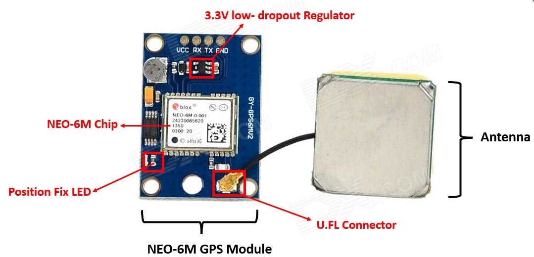
NEO-6M GPS Chip
In the middle of the GPS module, you can find the NEO-6M chip. This is responsible for tracking up to 22 satellites and any location on the Earth on several channels. Due to its highly sensitive tracking nature, it makes the NEO-6M module a popular GPS tracker.
Some key features of NEO-6M chip include:
- High sensitivity for tracking
- Low supply current (~45mA)
- Is able to track 5 locations per second with an accuracy of 2.5m (horizontal).
- Comes equipped with PSM also known as Power Saving Mode. This mode causes very less power consumption by turning the module ON/OFF according to the need.
- Great use as GPS trackers in smart watches due to very low power consumption (~11mA)
Position Fix LED Indicator
Moving ahead, the module comes with a position fix LED indicator. This LED indicates through its blinking effect whether the module is searching for satellites or has already found them. If the LED blinks after every second, then it indicates that the position fix is found. However, if the LED does not blink then the module is still searching for the satellites.
3.3V low-dropout Regulator
The module also comes equipped with a 3.3V LDO regulator (MIC5205). This provides an efficient linear voltage regulation with ultralow-noise output and very low dropout voltage. Additionally, the module is can also tolerate 5V easily.
Specifications
The table below shows some specifications of the NEO-6M module.
| Type | GPS |
|---|---|
| Supply | 2.7 V-3.6 V |
| Operating Current | 45mA |
| Operating Temperature | -40°C ~ 85°C |
| Horizontal Position Accuracy | 2.5m |
| Communication Protocol | NMEA, UBX Binary, RTCM |
| Features | RTC Crystal and External Interrupt/Wake up |
| Interface | UART, SPI, USB and DDC |
For more information regarding the NEO-6M module refer to its datasheet given here.
Pinout of NEO 6M Module
The diagram below shows the pinout of the NEO 6M module. It consists of 4 pins named GND, TX, RX, and VCC.
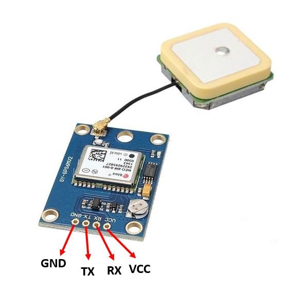
| GND | This is the ground pin that will be connected with the ground of the microcontroller. |
| TX | This is the transmission pin used for serial communication. |
| RX | This is the receiver pin used for serial communication. |
| VCC | This is the VCC pin used to power up the GPS module. |
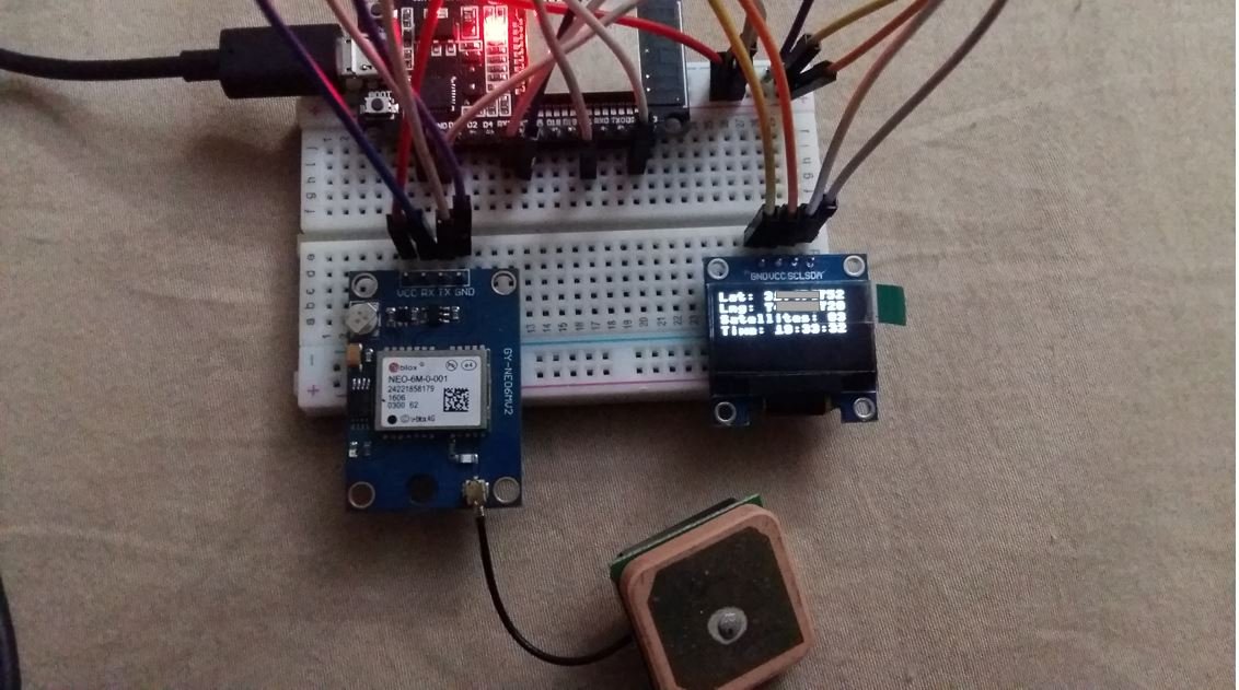
Interfacing NEO-6M Module with ESP32 and OLED
We will need the following components to connect our ESP32 development board with the OLED Display and NEO-6M GPS module.
- ESP32 development board
- NEO-6M GPS Module
- SSD1306 OLED Display
- Connecting Wires
ESP32 with NEO-6M and OLED
The OLED display has 4 terminals which we will connect with the ESP32 board. As the OLED display requires an operating voltage in the range of 3.3-5V hence we will connect the VCC terminal with 3.3V which will be in common with the ESP32 board. SCL of the display will be connected with the SCL pin of the module and the SDA of the display will be connected with the SDA of the module. By default, the I2C pin in ESP32 for SDA is GPIO21, and for SCL is GPIO22. The connections between the two devices can be seen in the table below.
| SSD1306 OLED Display | ESP32 |
|---|---|
| VCC | 3.3V |
| SDA | GPIO21(I2C SDA) |
| SCL | GPIO22(I2C SCL) |
| GND | GND |
Similarly, the NEO-6M GPS module also has 4 terminals which we will connect with the ESP32 board. As the GPS module requires an operating voltage in the range of 2.7-3.6V hence we will connect the VCC terminal with 3.3V which will be in common with the ESP32 board. The TX (transmitter) terminal of the GPS module will be connected with the RX2 pin of the ESP32 for communication. Likewise, the RX (receiver) terminal of the GPS module will be connected with the TX2 pin of the ESP32.
| ESP32 | NEO-6M Module |
|---|---|
| 3.3V | VCC |
| RX2 | TX |
| TX2 | RX |
| GND | GND |
All three devices will be commonly grounded.
The diagram below shows the schematic diagram of ESP32 with OLED display and NEO 6M Module.


Understanding basic NMEA sentence
The NEO-6M GPS module sends GPS data in NMEA format. It is of various kinds including $GPRMC, $GPGGA etc. Each NMEA data field is separated by a comma and starts with a ‘$’.
Below you can view the $GPXXX syntax that denotes the different types of NMEA messages:
| $GPGGA | Global Positioning System Fix Data. It provides 3D location and accuracy data |
| $GPGSA | It provides GPS DOP and active satellites |
| $GPGSV | It provides the detailed information of the GPS satellite |
| $GPGLL | It provides the geographic Latitude and Longitude |
| $GPRMC | It provides the position, velocity and time |
| $GPVTG | It provides the dual ground/water speed |
Let us understand how to read the basic NMEA sentence i.e. $GPGGA. Here is an example $GPGGA NMEA sentence:
$GPGGA, 103005, 3807.038, N, 07128.99030, E, 1, 07, 1.43, 134.5, M, 42.9, M, , *78- $: This indicates the start of the NMEA sentence
- GPGGA : Global Positioning System Fix Data
- 103005 : This is the UTC time when the data was accessed in HH:MM:SS. In this case the time is 10:30:05 UTC
- 3807.038, N : Latitude 38 degrees 07.038′ N
- 07128.99030, E : Longitude 71 degrees 28.00030′ E
- 1 : GPS fix
- 07 : Number of satellites being tracked
- 1.43 : Horizontal dilution of position
- 134.5, M : This shows the altitude (m) above the sea level
- 42.9, M : Height of geoid (mean sea level)
- Empty field : time in seconds since last DGPS update
- Empty field : DGPS station ID number
- *78 : the checksum data
SSD1306 OLED MicroPython Library
We will have to install the SSD1306 OLED library for MicroPython to continue with our project.
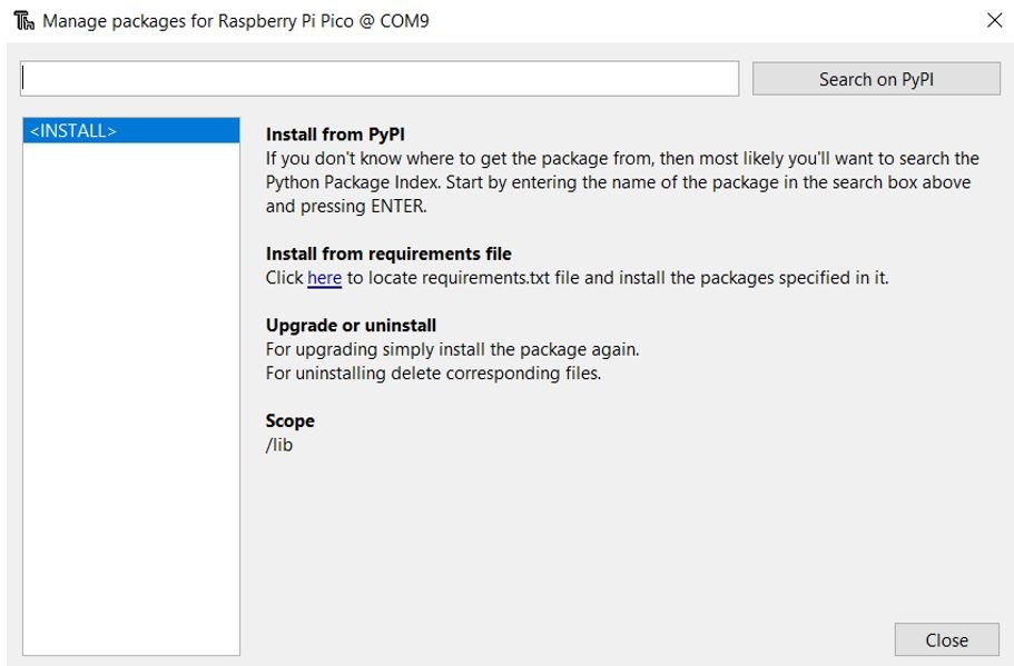
- To successfully do that, open your Thonny IDE with your ESP32 or ESP8266 plugged in your system. Go to Tools > Manage Packages. This will open up the Thonny Package Manager.
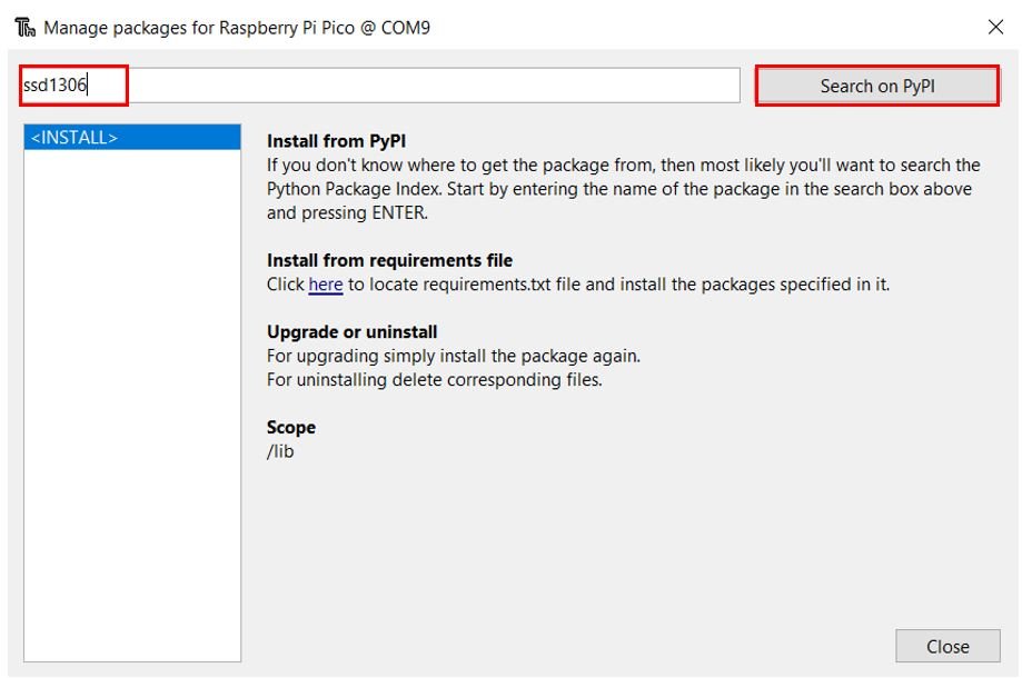
- Search for “ssd1306” in the search bar by typing its name and clicking the button ‘Search on PyPI.’
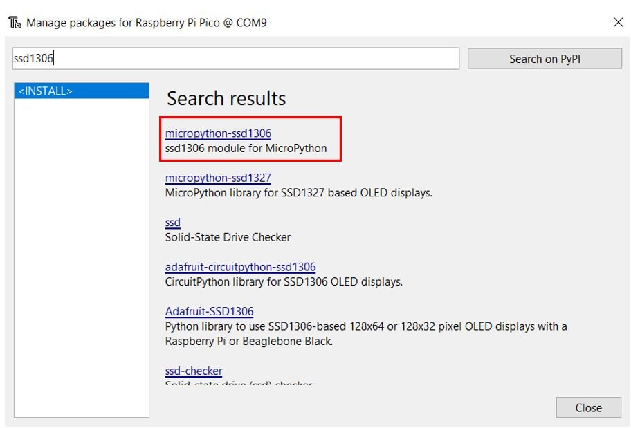
- From the following search results click on the one highlighted below: micropython-ssd1306
Install this library.
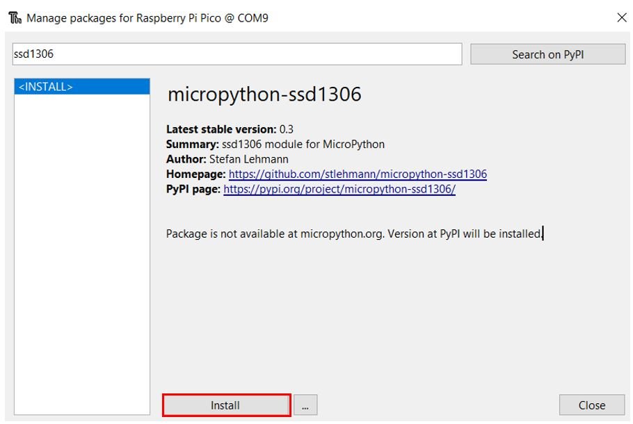
After a few moments this library will get successfully installed. Now we are ready to program our ESP32 with OLED display.
MicroPython Script Obtaining GPS Data from NEO-6M Module
from machine import Pin, UART, SoftI2C
from ssd1306 import SSD1306_I2C

import utime, time

i2c = SoftI2C(scl=Pin(22), sda=Pin(21), freq=10000)     #initializing the I2C method for ESP32

oled = SSD1306_I2C(128, 64, i2c)

gpsModule = UART(2, baudrate=9600)
print(gpsModule)

buff = bytearray(255)

TIMEOUT = False
FIX_STATUS = False

latitude = ""
longitude = ""
satellites = ""
GPStime = ""

def getGPS(gpsModule):
    global FIX_STATUS, TIMEOUT, latitude, longitude, satellites, GPStime

    timeout = time.time() + 8
    while True:
        gpsModule.readline()
        buff = str(gpsModule.readline())
        parts = buff.split(',')

        if (parts[0] == "b'$GPGGA" and len(parts) == 15):
            if(parts[1] and parts[2] and parts[3] and parts[4] and parts[5] and parts[6] and parts[7]):
                print(buff)

                latitude = convertToDegree(parts[2])
                if (parts[3] == 'S'):
                    latitude = -latitude
                longitude = convertToDegree(parts[4])
                if (parts[5] == 'W'):
                    longitude = -longitude
                satellites = parts[7]
                GPStime = parts[1][0:2] + ":" + parts[1][2:4] + ":" + parts[1][4:6]
                FIX_STATUS = True
                break

        if (time.time() > timeout):
            TIMEOUT = True
            break
        utime.sleep_ms(500)

def convertToDegree(RawDegrees):

    RawAsFloat = float(RawDegrees)
    firstdigits = int(RawAsFloat/100)
    nexttwodigits = RawAsFloat - float(firstdigits*100)

    Converted = float(firstdigits + nexttwodigits/60.0)
    Converted = '{0:.6f}'.format(Converted)
    return str(Converted)


while True:

    getGPS(gpsModule)

    if(FIX_STATUS == True):
        print("Printing GPS data...")
        print(" ")
        print("Latitude: "+latitude)
        print("Longitude: "+longitude)
        print("Satellites: " +satellites)
        print("Time: "+GPStime)
        print("----------------------")

        oled.fill(0)
        oled.text("Lat: "+latitude, 0, 0)
        oled.text("Lng: "+longitude, 0, 10)
        oled.text("Satellites: "+satellites, 0, 20)
        oled.text("Time: "+GPStime, 0, 30)
        oled.show()

        FIX_STATUS = False

    if(TIMEOUT == True):
        print("No GPS data is found.")
        TIMEOUT = False
How the Code Works?
We will start by importing the UART, Pin and SoftI2C class from the machine module. Next we will also import utime and time module to incorporate delays. We will also import the ssd1306 which is the OLED display library that we installed earlier. This will help us in accessing all the functions defined inside it.
from machine import Pin, UART, SoftI2C
from ssd1306 import SSD1306_I2C
import utime, time
Initializing OLED
Next, we will initialize the I2C GPIO pins for SCL and SDA respectively.
We have created an I2C() method which takes in three parameters. The first parameter specifies the I2C GPIO pin of the board which is connected to the SCL line. The second parameter specifies the I2C GPIO pin of the board which is connected to the SDA line. The last parameter is the frequency connection of the OLED.
We are setting the SCL on GPIO22 and the SDA on GPIO21.
i2c = SoftI2C(scl=Pin(22), sda=Pin(21), freq=10000) This SCL and SDA pin data gets saved in the object ‘i2c’ which will connect to the I2C bus and help in the communication between the two devices
Now, we will create an object ‘oled’ of SSD1306_I2C which uses the width, height, and the i2c object as parameters.
oled = SSD1306_I2C(128, 64, i2c)Initialize UART Communication
Then we will define the NEO-6M UART connection by creating an object ‘gpsModule’. By using UART() we specified the UART channel as the first parameter and the baud rate as the second parameter. We are using UART2 in this case with baud rate 9600 for the uart communication.
Then we will print these NEO-6M module connection details in the Thonny shell console.
gpsModule = UART(2, baudrate=9600)
print(gpsModule)
Data Variables
Then we will create a byte array object called buff to store the NMEA sentences.
buff = bytearray(255)The following variables will store the GPS parameters including Latitude, Longitude, Number of satellites and UTC time.
latitude = ""
longitude = ""
satellites = ""
GPStime = ""
The following function obtains the GPS coordinates. We are running a while loop to obtain the GPS data from the basic NMEA sentence $GPGGA. Latitude, Longitude, Satellites and time will be acquired from the NMEA sentence accordingly and saved in their respective variables.
def getGPS(gpsModule):
    global FIX_STATUS, TIMEOUT, latitude, longitude, satellites, GPStime

    timeout = time.time() + 8
    while True:
        gpsModule.readline()
        buff = str(gpsModule.readline())
        parts = buff.split(',')

        if (parts[0] == "b'$GPGGA" and len(parts) == 15):
            if(parts[1] and parts[2] and parts[3] and parts[4] and parts[5] and parts[6] and parts[7]):
                print(buff)

                latitude = convertToDegree(parts[2])
                if (parts[3] == 'S'):
                    latitude = -latitude
                longitude = convertToDegree(parts[4])
                if (parts[5] == 'W'):
                    longitude = -longitude
                satellites = parts[7]
                GPStime = parts[1][0:2] + ":" + parts[1][2:4] + ":" + parts[1][4:6]
                FIX_STATUS = True
                break

        if (time.time() > timeout):
            TIMEOUT = True
            break
        utime.sleep_ms(500)
The following function is responsible to convert the raw longitude and latitude data to actual values.
def convertToDegree(RawDegrees):

    RawAsFloat = float(RawDegrees)
    firstdigits = int(RawAsFloat/100)
    nexttwodigits = RawAsFloat - float(firstdigits*100)

    Converted = float(firstdigits + nexttwodigits/60.0)
    Converted = '{0:.6f}'.format(Converted)
    return str(Converted)
Inside the infinite loop we will call the getGPS(gpsModule) function first. If the GPS data is available then print it both on the Thonny shell console and the OLED display. If the GPS data is not acquired within the time set within the program, then “No GPS data is found” message is printed on the shell console instead.
while True:

    getGPS(gpsModule)

    if(FIX_STATUS == True):
        print("Printing GPS data...")
        print(" ")
        print("Latitude: "+latitude)
        print("Longitude: "+longitude)
        print("Satellites: " +satellites)
        print("Time: "+GPStime)
        print("----------------------")

        oled.fill(0)
        oled.text("Lat: "+latitude, 0, 0)
        oled.text("Lng: "+longitude, 0, 10)
        oled.text("Satellites: "+satellites, 0, 20)
        oled.text("Time: "+GPStime, 0, 30)
        oled.show()

        FIX_STATUS = False

    if(TIMEOUT == True):
        print("No GPS data is found.")
        TIMEOUT = False
Demo
After you have copied the following code onto a new file, click the ‘Save’ icon to save your program code on your PC.
After you have saved the code press the Run button to upload the code to your board. Before uploading code make sure the correct board is selected.
In the shell terminal of your IDE, you will be able to view the following GPS parameters:

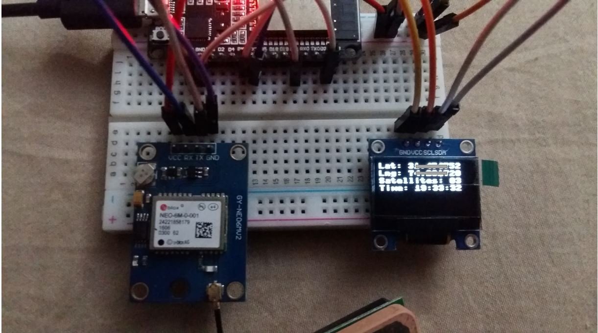
Once the code is uploaded to ESP32, you will be able to view the GPS data on the OLED as well:
To read more GPS related articles, follow the links below:
- NEO-6M GPS Module with ESP8266 NodeMCU and Track Location on Google Maps
- ESP32 GPS tracker – IoT based Vehicle Tracking System
- GPS Data Logger with Arduino and Micro SD Card – GPS Tracker
- Interface NEO-6M GPS Module with Arduino
- Display GPS Co-ordinates on LCD using pic microcontroller
- Interfacing GPS module with Arduino: GPS coordinates on Lcd
- Vehicle Tracking System Through GPS-GSM Modules
Hello,
Thank you for this tuto. At least for ESP8266, it may be useful do detach UART(0) from REPL, otherwise GPS module will send sentence to terminal, which would try to interpret this as micropython commands.
import os
os.dupterm(None, 1)
Don’t forget to attach UART(0) when finished :
import os, machine
uart = machine.UART(0, 115200)
os.dupterm(uart, 1)
See docs.micropython.org.
Thank you for this interesting tutorial. I just came across with an issue due to my location. I am actually in Buenos Aires, Argentina and the script gives an error because the city is in the southern hemisphere an in the west of Greenwich meridian. The scrip requires to convert the coordinates from positive to negative and then it gives the following error:
Traceback (most recent call last):
File “”, line 65, in
File “”, line 38, in getGPS
TypeError: unsupported type for __neg__: ‘str’
Best regards
Gustavo
(continue)
A quick and dirty solution could be:
to replace the line:
latitude = -latitude
by:
latitude = str(-float(latitude))
And replace:
latitude = -latitude
by:
latitude = str(-float(latitude))
Best regards
or else:
latitude = ‘-‘+latitude
thank you very much for the tutorial
how to use this for esp8266
One thing to note: Most (if not all) of the affordable NEO-6M modules available (definitely including the one in the tutorial) are counterfeit ones from China. The chip under the cover is an AT6558 one (instead of a NEO-6M) and if one wants to use the U-Blox utilities or special NEO-6M commands like low-power mode, they will not work. One rule of thumb: a blue, red or black is always counterfeit. Only the green PCBs may be valid. Also, in the original product, there is a lighter-coloured border around the red logo and the black circle. If you do not believe me, Google for “counterfeit NEO-6M” for further info.
I have a counterfeit one, and it looks exactly the same as the one in the photos.
I believe the unit will work if you only want to use the default settings the same way as in this tutorial (which was very nice, thanks for that).