In this tutorial, we will learn to interface STM32 Blue Pill with 4-digit 7 segment display and program it in STM32CubeIDE. Firstly, we will introduce you to the 4-digit 7 segment display, its connection with the STM32 Blue Pill and then move forward to create and build a counter display in Cube IDE. The counter will display numbers from 0-9999 on our 4-digit seven segment display continuously.
Recommended Components
The following components are used in this project or are helpful for getting started with STM32 Blue Pill development.
| Component | How it’s used in this project | Buy on Amazon |
|---|---|---|
| STM32F103C8T6 Blue Pill Board | The STM32 development board driving the display. | Check Price |
| ST-Link V2 Programmer | Flashes the compiled code onto the Blue Pill via SWD. | Check Price |
| 4-Digit 7-Segment Display | The 4-digit common-cathode display used for the counter. | Check Price |
| Resistor Kit (incl. 220Ω) | Eleven 220Ω current-limiting resistors for the segments and digits. | Check Price |
| Breadboard | Solderless breadboard for building the circuit. | Check Price |
| Jumper Wires | Male-to-male / male-to-female wires for the connections. | Check Price |
As an Amazon Associate we earn from qualifying purchases. Prices and availability are accurate as of the date/time indicated and are subject to change.
7 Segment Display Introduction
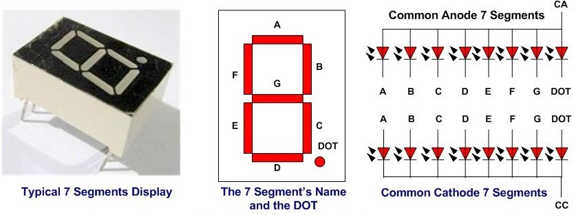
A 7-segment device consists of 7 light emitting diodes. These light-emitting diodes are arranged and packed inside a single display with a specific pattern in mind. If this pattern is controlled in a specific way by turning on and turning off LEDs, a seven-segment device will display a unique number. There is also an extra eighth LED on a seven-segment display which is used to display dots. This dot is sometimes used as a decimal point when we want to display a fractional value.
The picture below shows a 7 segment display and its pinout. The string of eight LEDs on the left side shows the internal connection and a picture on the right side shows how these LEDs are arranged to make a seven-segment display. Pin3 and 8 are common pins. These pins are used to provide either 5 volt or ground in common-anode and common cathode type displays respectively.
Types of Seven Segment Displays
There are two types of seven segment displays such as common anode and common cathode.
Common Anode Display
In a common anode display, all the anodes terminals of eight light emitting diodes are common and connect with 5 volt power supply. In normal condition, we apply logic high from our microcontroller to each segment. Therefore, each segment remains off or does not glow. Similarly, when we want to turn on a specific LED of a seven-segment device, we provide logic low signal. Because LED glows only when there will be a logic high signal on anode side and logic low signal on cathode side such is the case of common anode type display.
Common Cathode Display
In common cathode segment display, all the cathodes of eight light emitting diodes are common and connect with the ground. In order to turn off any segment of 7-segment, we apply logic low from our microcontroller to this segment. Similarly, when we want to turn on a specific LED of a seven-segment device, we provide a logic high signal from the microcontroller digital output pin. Because LED glows only when there will be a logic high signal on anode side and logic low signal on cathode side such is the case of common cathode type display.
Recommended Reading: Seven Segment Display Interfacing with Arduino
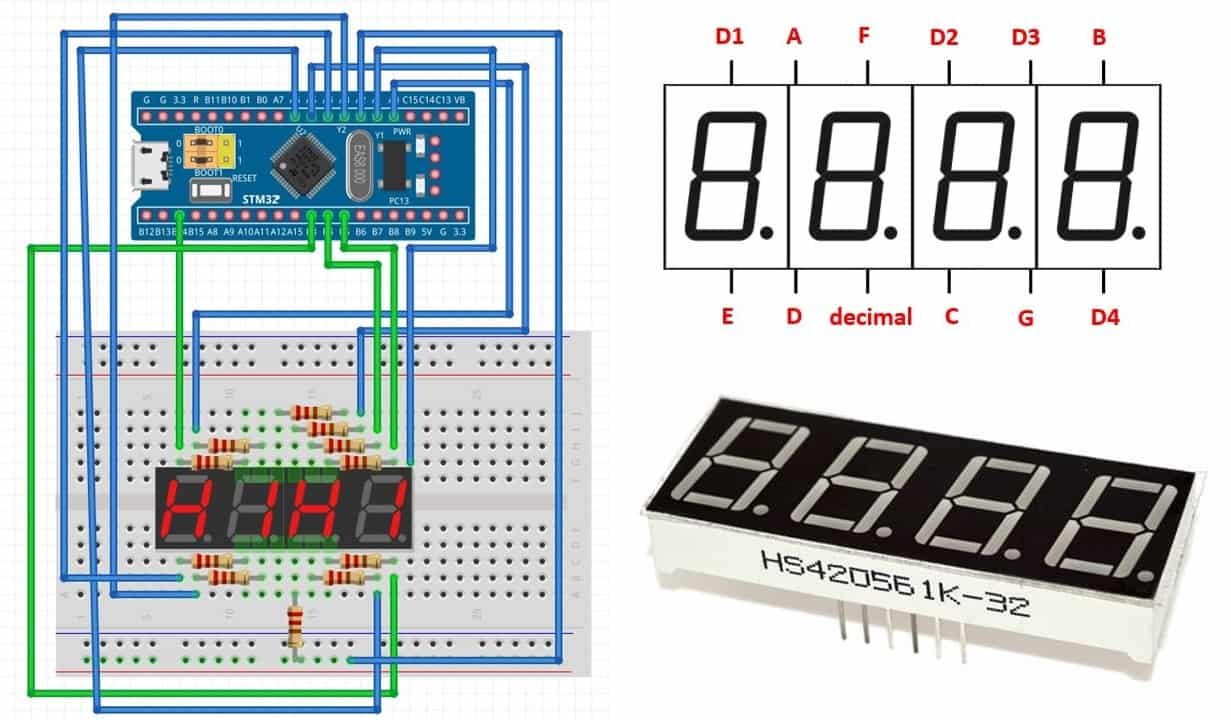
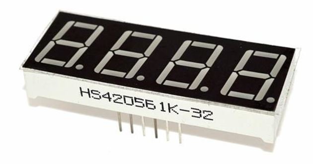
HS420561K-32 4-digit 7 segment display
A 4-digit 7 segment display we will use in this guide is shown below:
It comes with 12 pins, 6 on either sides. The figure below shows its pin configuration.
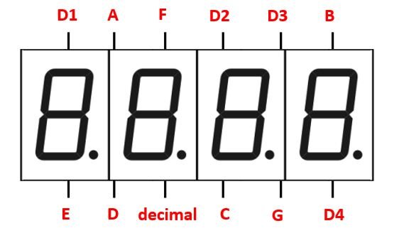
The table below shows the pin number associated with each segment.
| Pin Number | Segment |
|---|---|
| 1 | E |
| 2 | D |
| 3 | decimal |
| 4 | C |
| 5 | G |
| 6 | D4 |
| 7 | B |
| 8 | D3 |
| 9 | D2 |
| 10 | F |
| 11 | A |
| 12 | D1 |
This is a common cathode display. Each segment pin for example A, B, C, D, E, F, G and decimal is responsible for controlling the same segments for all the digits. The digit pins are separate D1, D2, D3 and D4 and are connected to its respective digit1-digit4 respectively. As it is common cathode configuration thus sending a LOW signal to the digit pin turns it ON. Therefore to control each digit we will have to first turn ON/OFF the digit pin D1-D4 of each of the digit. This will be done by providing a HIGH signal to the digit pin. Then we will have to turn on the individual segments to display a number.
Interfacing STM32 Blue Pill with 4-digit 7 segment display
The following components are required for this project:
- STM32 Blue Pill board
- 4-digit 7 segment display
- Eleven 220 ohm resistors
- Connecting Wires
- Breadboard
In order to properly connect all the devices successfully follow the connections very carefully. Follow the schematic diagram below:

Lets discuss the connections between STM32 Blue Pill and the 4-digit 7 segment display. Use four digital output pins of STM32 to connect with each of the digit pin D1-D4 through current limiting resistors of 220 ohms each. Likewise, use six digital output pins of STM32 to connect with each of the segment pins A-G through current limiting resistors of 220 ohms.
We have used the pins specified in the table below.
| 4-digit 7 segment Display | STM32 Blue Pill |
|---|---|
| D1 | PB14 |
| D2 | PB4 |
| D3 | PB5 |
| D4 | PB3 |
| A | PA0 |
| B | PA1 |
| C | PA2 |
| D | PA3 |
| E | PA4 |
| F | PA5 |
| G | PA6 |
STM32 Blue Pill 4-Digit 7 Segment Display Counter Project
Let’s create and build a project in STM32 CubeIDE through which we will be able to build a counter on our 4-digit 7 segment display using STM32 Blue Pill
Open the CubeIDE and head over to a new project.
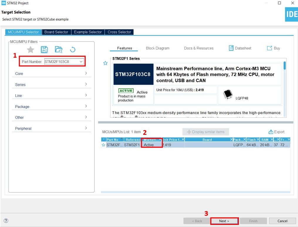
Then for the target selection, specify the STM32 Blue Pill board number. After that click on any column as shown in the picture below. Then click the ‘Next’ button.
Specify the name of your project then click ‘Finish’ to complete the setup of your project.
Go to System Core > RCC then select ‘Crystal/Ceramic Resonator’ in from the High Speed Clock feature.
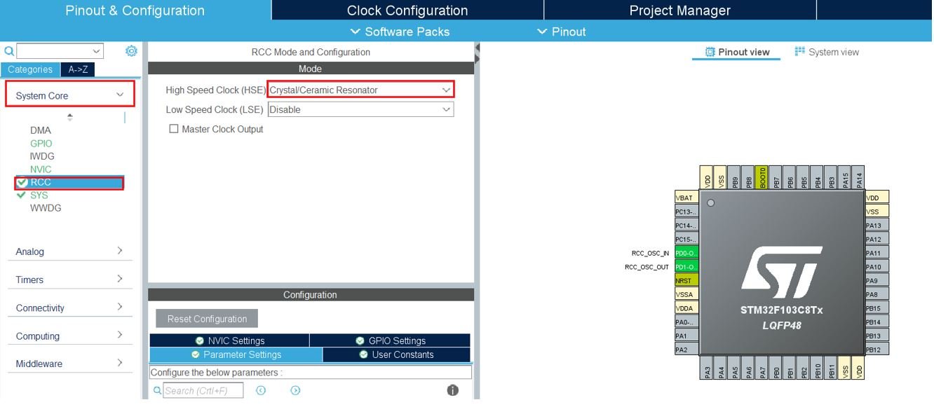
Now we have enabled the RCC external clock source.
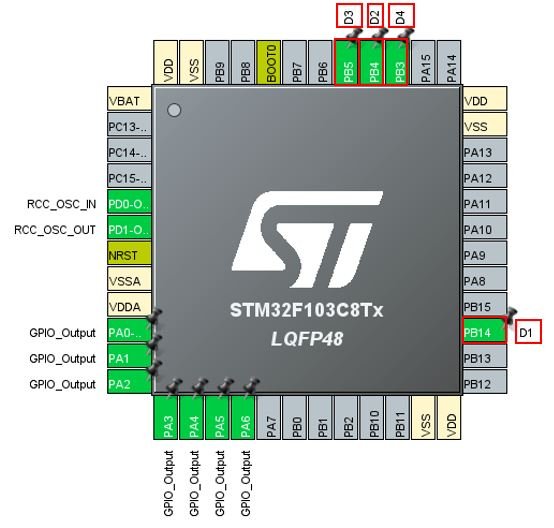
Setup pins PA0-PA6 as GPIO_Output pins. These are the pins that will be connected with A-G segment pins of the display.

Now setup PB14, PB4, PB5, PB3 as GPIO_Output pins and label them as D1-D4 respectively.
Clock Configuration
Next go to the Clock Configuration found at the top. This will open the following window. Here we will select the clock frequency.
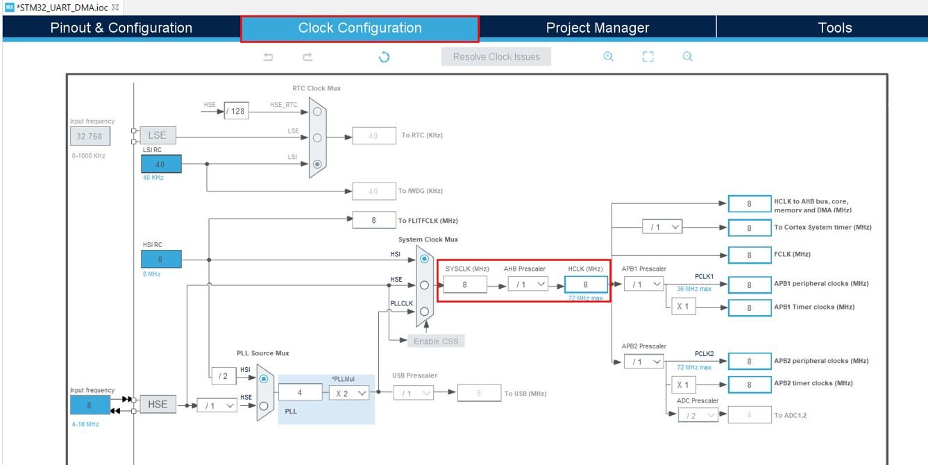
You can specify your system clock. We will set it as 72 MHz. These are the configurations we have set:

Now we will save our file. Press Ctrl + S. The following window will appear. Click ‘Yes.’ This will generate a template code for you.

Another window will appear that will ask if you want to open the perspective. Click ‘Yes.’

STM32 4-Digit 7 Segment Display Counter Code
We will set up a code in which the 4-digit 7 segment display will print out numbers from 0-9999 continuously in a loop.
Now let us look at our main.c file that was generated. Inside the main.c file, make sure the following code is part of your script by including the lines of code given below.
#include "main.h"

void SystemClock_Config(void);
static void MX_GPIO_Init(void);

uint32_t counter = 0;
uint8_t temp1, temp2, temp3, temp4;

#define D1_HIGH HAL_GPIO_WritePin(GPIOB, GPIO_PIN_14, GPIO_PIN_SET);
#define D1_LOW HAL_GPIO_WritePin(GPIOB, GPIO_PIN_14, GPIO_PIN_RESET);

#define D2_HIGH HAL_GPIO_WritePin(GPIOB, GPIO_PIN_4, GPIO_PIN_SET);
#define D2_LOW HAL_GPIO_WritePin(GPIOB, GPIO_PIN_4, GPIO_PIN_RESET);

#define D3_HIGH HAL_GPIO_WritePin(GPIOB, GPIO_PIN_5, GPIO_PIN_SET);
#define D3_LOW HAL_GPIO_WritePin(GPIOB, GPIO_PIN_5, GPIO_PIN_RESET);

#define D4_HIGH HAL_GPIO_WritePin(GPIOB, GPIO_PIN_3, GPIO_PIN_SET);
#define D4_LOW HAL_GPIO_WritePin(GPIOB, GPIO_PIN_3, GPIO_PIN_RESET);

uint8_t segmentNumber[10]={
		0x3f,
		0x06,
		0x5b,
		0x4f,
		0x66,
		0x6d,
		0x7d,
		0x07,
		0x7f,
		0x67
};

void SevenSegment_Update(uint8_t number){
	HAL_GPIO_WritePin(GPIOA, GPIO_PIN_0, ((number>>0)&0x01));
	HAL_GPIO_WritePin(GPIOA, GPIO_PIN_1, ((number>>1)&0x01));
	HAL_GPIO_WritePin(GPIOA, GPIO_PIN_2, ((number>>2)&0x01));
	HAL_GPIO_WritePin(GPIOA, GPIO_PIN_3, ((number>>3)&0x01));
	HAL_GPIO_WritePin(GPIOA, GPIO_PIN_4, ((number>>4)&0x01));
	HAL_GPIO_WritePin(GPIOA, GPIO_PIN_5, ((number>>5)&0x01));
	HAL_GPIO_WritePin(GPIOA, GPIO_PIN_6, ((number>>6)&0x01));
}

int main(void)
{
  HAL_Init();

  SystemClock_Config();

  MX_GPIO_Init();

  HAL_GPIO_WritePin(GPIOA, GPIO_PIN_0, GPIO_PIN_RESET);
  HAL_GPIO_WritePin(GPIOA, GPIO_PIN_1, GPIO_PIN_RESET);
  HAL_GPIO_WritePin(GPIOA, GPIO_PIN_2, GPIO_PIN_RESET);
  HAL_GPIO_WritePin(GPIOA, GPIO_PIN_3, GPIO_PIN_RESET);
  HAL_GPIO_WritePin(GPIOA, GPIO_PIN_4, GPIO_PIN_RESET);
  HAL_GPIO_WritePin(GPIOA, GPIO_PIN_5, GPIO_PIN_RESET);
  HAL_GPIO_WritePin(GPIOA, GPIO_PIN_6, GPIO_PIN_RESET);

  HAL_GPIO_WritePin(GPIOB, D1_Pin|D4_Pin|D2_Pin|D3_Pin, GPIO_PIN_SET);


  while (1)
  {
	  temp1 = counter/1000;
	  temp2 = ((counter/100)%10);
	  temp3 = ((counter/10)%10);
	  temp4 = (counter%10);

	  SevenSegment_Update(segmentNumber[temp1]);
	  D1_LOW;
	  HAL_Delay(7);
	  D1_HIGH;

	  SevenSegment_Update(segmentNumber[temp2]);
	  D2_LOW;
	  HAL_Delay(7);
	  D2_HIGH;

	  SevenSegment_Update(segmentNumber[temp3]);
	  D3_LOW;
	  HAL_Delay(7);
	  D3_HIGH;

	  SevenSegment_Update(segmentNumber[temp4]);
	  D4_LOW;
	  HAL_Delay(7);
	  D4_HIGH;

	  counter++;
	  if (counter >= 1000){
		  counter = 0;
	  }
	 HAL_Delay(1000);

  }

}
Working of the Code
First we create a variable called ‘counter’ and initialize it to zero. Moreover, we create four more variables called ‘temp1′,’temp2′,’temp3’ and ‘temp4’ which will store the first, second, third and fourth digit values.
uint32_t counter = 0;
uint8_t temp1, temp2, temp3, temp4;
Next, we define D1_HIGH, D1_LOW, D2_HIGH, D2_LOW, D3_HIGH, D3_LOW, D4_HIGH and D4_LOW. These will be used to turn each of the digit pins state to high or low through the function HAL_GPIO_WritePin(). This function sets or clears the selected data port bit by taking in the selected GPIO peripheral as the first parameter, GPIO port bit as the second parameter and the pin state as the third parameter.
#define D1_HIGH HAL_GPIO_WritePin(GPIOB, GPIO_PIN_14, GPIO_PIN_SET);
#define D1_LOW HAL_GPIO_WritePin(GPIOB, GPIO_PIN_14, GPIO_PIN_RESET);

#define D2_HIGH HAL_GPIO_WritePin(GPIOB, GPIO_PIN_4, GPIO_PIN_SET);
#define D2_LOW HAL_GPIO_WritePin(GPIOB, GPIO_PIN_4, GPIO_PIN_RESET);

#define D3_HIGH HAL_GPIO_WritePin(GPIOB, GPIO_PIN_5, GPIO_PIN_SET);
#define D3_LOW HAL_GPIO_WritePin(GPIOB, GPIO_PIN_5, GPIO_PIN_RESET);

#define D4_HIGH HAL_GPIO_WritePin(GPIOB, GPIO_PIN_3, GPIO_PIN_SET);
#define D4_LOW HAL_GPIO_WritePin(GPIOB, GPIO_PIN_3, GPIO_PIN_RESET);
Next we specify the segmentNumber array. This consists of hex values of binary patterns according to the number that we want to display. Here we define an unsigned 8-bit integer type array that consists of 10 characters type numbers 0-9.
uint8_t segmentNumber[10]={
		0x3f,
		0x06,
		0x5b,
		0x4f,
		0x66,
		0x6d,
		0x7d,
		0x07,
		0x7f,
		0x67
};
The SevenSegment_Update() function takes an unsigned 8-bit integer number as a parameter inside it. It will update the number on the 7 segment display. Inside the function we will acquire the individual bits of the number and send them to the corresponding pins. This will be accomplished by using HAL_GPIO_WritePin() function which takes in the selected GPIO peripheral as the first parameter, GPIO port bit as the second parameter and the pin state as the third parameter. For the pin state we will right shift the number to the corresponding pin.
void SevenSegment_Update(uint8_t number){
	HAL_GPIO_WritePin(GPIOA, GPIO_PIN_0, ((number>>0)&0x01));
	HAL_GPIO_WritePin(GPIOA, GPIO_PIN_1, ((number>>1)&0x01));
	HAL_GPIO_WritePin(GPIOA, GPIO_PIN_2, ((number>>2)&0x01));
	HAL_GPIO_WritePin(GPIOA, GPIO_PIN_3, ((number>>3)&0x01));
	HAL_GPIO_WritePin(GPIOA, GPIO_PIN_4, ((number>>4)&0x01));
	HAL_GPIO_WritePin(GPIOA, GPIO_PIN_5, ((number>>5)&0x01));
	HAL_GPIO_WritePin(GPIOA, GPIO_PIN_6, ((number>>6)&0x01));
}
Inside the main() function, first the all the peripherals are initialized, system clock is configured and all the configured peripherals are initialized.
  HAL_Init();
  SystemClock_Config();

  MX_GPIO_Init();
Then, we will initialize the states of the segment pins A-G as LOW and the digit pins D1-D4 as HIGH. This is because our seven-segment is common cathode which turns on with active low signals. Therefore, at the start, we initialize the digit control signals as active high.
  HAL_GPIO_WritePin(GPIOA, GPIO_PIN_0, GPIO_PIN_RESET);
  HAL_GPIO_WritePin(GPIOA, GPIO_PIN_1, GPIO_PIN_RESET);
  HAL_GPIO_WritePin(GPIOA, GPIO_PIN_2, GPIO_PIN_RESET);
  HAL_GPIO_WritePin(GPIOA, GPIO_PIN_3, GPIO_PIN_RESET);
  HAL_GPIO_WritePin(GPIOA, GPIO_PIN_4, GPIO_PIN_RESET);
  HAL_GPIO_WritePin(GPIOA, GPIO_PIN_5, GPIO_PIN_RESET);
  HAL_GPIO_WritePin(GPIOA, GPIO_PIN_6, GPIO_PIN_RESET);

  HAL_GPIO_WritePin(GPIOB, D1_Pin|D4_Pin|D2_Pin|D3_Pin, GPIO_PIN_SET);
Inside the while loop, we will display the digits from 0-9999 on the 4-digit seven segment display as a counter. We are separating the number into 4 individual digits. Here ‘temp1’ stores the 1000th digit vale, ‘temp2’ holds the 100th digit value, ‘temp3’ holds the 10th digit value and ‘temp4’ holds the unit digit value. These digits will be displayed on the 4-digit seven segment display where temp1 is the first digit, temp2 is the second digit, temp3 is the third digit and temp4 is the fourth digit of the 4-digit display.
After extracting the digits, the SevenSegment_Update() function is called and passed the segmentNumber[] array as a parameter inside it with the first, second, third and fourth digit one at a time. The array For common cathode display, to display a number, D1-D4 should be set from LOW to HIGH. A delay of 7ms is included between the state transitions. The counter value is incremented till 9999 and then reset to 0. All of this occurs inside the infinite while loop.
  while (1)
  {
	  temp1 = counter/1000;
	  temp2 = ((counter/100)%10);
	  temp3 = ((counter/10)%10);
	  temp4 = (counter%10);

	  SevenSegment_Update(segmentNumber[temp1]);
	  D1_LOW;
	  HAL_Delay(7);
	  D1_HIGH;

	  SevenSegment_Update(segmentNumber[temp2]);
	  D2_LOW;
	  HAL_Delay(7);
	  D2_HIGH;

	  SevenSegment_Update(segmentNumber[temp3]);
	  D3_LOW;
	  HAL_Delay(7);
	  D3_HIGH;

	  SevenSegment_Update(segmentNumber[temp4]);
	  D4_LOW;
	  HAL_Delay(7);
	  D4_HIGH;

	  counter++;
	  if (counter >= 1000){
		  counter = 0;
	  }
	 HAL_Delay(1000);

  }
main.c file
This is how a complete main.c file will be after modification.
#include "main.h"

void SystemClock_Config(void);
static void MX_GPIO_Init(void);

uint32_t counter = 0;
uint8_t temp1, temp2, temp3, temp4;

#define D1_HIGH HAL_GPIO_WritePin(GPIOB, GPIO_PIN_14, GPIO_PIN_SET);
#define D1_LOW HAL_GPIO_WritePin(GPIOB, GPIO_PIN_14, GPIO_PIN_RESET);

#define D2_HIGH HAL_GPIO_WritePin(GPIOB, GPIO_PIN_4, GPIO_PIN_SET);
#define D2_LOW HAL_GPIO_WritePin(GPIOB, GPIO_PIN_4, GPIO_PIN_RESET);

#define D3_HIGH HAL_GPIO_WritePin(GPIOB, GPIO_PIN_5, GPIO_PIN_SET);
#define D3_LOW HAL_GPIO_WritePin(GPIOB, GPIO_PIN_5, GPIO_PIN_RESET);

#define D4_HIGH HAL_GPIO_WritePin(GPIOB, GPIO_PIN_3, GPIO_PIN_SET);
#define D4_LOW HAL_GPIO_WritePin(GPIOB, GPIO_PIN_3, GPIO_PIN_RESET);

uint8_t segmentNumber[10]={
		0x3f,
		0x06,
		0x5b,
		0x4f,
		0x66,
		0x6d,
		0x7d,
		0x07,
		0x7f,
		0x67
};

void SevenSegment_Update(uint8_t number){
	HAL_GPIO_WritePin(GPIOA, GPIO_PIN_0, ((number>>0)&0x01));
	HAL_GPIO_WritePin(GPIOA, GPIO_PIN_1, ((number>>1)&0x01));
	HAL_GPIO_WritePin(GPIOA, GPIO_PIN_2, ((number>>2)&0x01));
	HAL_GPIO_WritePin(GPIOA, GPIO_PIN_3, ((number>>3)&0x01));
	HAL_GPIO_WritePin(GPIOA, GPIO_PIN_4, ((number>>4)&0x01));
	HAL_GPIO_WritePin(GPIOA, GPIO_PIN_5, ((number>>5)&0x01));
	HAL_GPIO_WritePin(GPIOA, GPIO_PIN_6, ((number>>6)&0x01));
}

int main(void)
{
  HAL_Init();

  SystemClock_Config();

  MX_GPIO_Init();

  HAL_GPIO_WritePin(GPIOA, GPIO_PIN_0, GPIO_PIN_RESET);
  HAL_GPIO_WritePin(GPIOA, GPIO_PIN_1, GPIO_PIN_RESET);
  HAL_GPIO_WritePin(GPIOA, GPIO_PIN_2, GPIO_PIN_RESET);
  HAL_GPIO_WritePin(GPIOA, GPIO_PIN_3, GPIO_PIN_RESET);
  HAL_GPIO_WritePin(GPIOA, GPIO_PIN_4, GPIO_PIN_RESET);
  HAL_GPIO_WritePin(GPIOA, GPIO_PIN_5, GPIO_PIN_RESET);
  HAL_GPIO_WritePin(GPIOA, GPIO_PIN_6, GPIO_PIN_RESET);

  HAL_GPIO_WritePin(GPIOB, D1_Pin|D4_Pin|D2_Pin|D3_Pin, GPIO_PIN_SET);


  while (1)
  {
	  temp1 = counter/1000;
	  temp2 = ((counter/100)%10);
	  temp3 = ((counter/10)%10);
	  temp4 = (counter%10);

	  SevenSegment_Update(segmentNumber[temp1]);
	  D1_LOW;
	  HAL_Delay(7);
	  D1_HIGH;

	  SevenSegment_Update(segmentNumber[temp2]);
	  D2_LOW;
	  HAL_Delay(7);
	  D2_HIGH;

	  SevenSegment_Update(segmentNumber[temp3]);
	  D3_LOW;
	  HAL_Delay(7);
	  D3_HIGH;

	  SevenSegment_Update(segmentNumber[temp4]);
	  D4_LOW;
	  HAL_Delay(7);
	  D4_HIGH;

	  counter++;
	  if (counter >= 1000){
		  counter = 0;
	  }
	 HAL_Delay(1000);

  }

}

/**
  * @brief System Clock Configuration
  * @retval None
  */
void SystemClock_Config(void)
{
  RCC_OscInitTypeDef RCC_OscInitStruct = {0};
  RCC_ClkInitTypeDef RCC_ClkInitStruct = {0};

  /** Initializes the RCC Oscillators according to the specified parameters
  * in the RCC_OscInitTypeDef structure.
  */
  RCC_OscInitStruct.OscillatorType = RCC_OSCILLATORTYPE_HSE;
  RCC_OscInitStruct.HSEState = RCC_HSE_ON;
  RCC_OscInitStruct.HSEPredivValue = RCC_HSE_PREDIV_DIV1;
  RCC_OscInitStruct.HSIState = RCC_HSI_ON;
  RCC_OscInitStruct.PLL.PLLState = RCC_PLL_ON;
  RCC_OscInitStruct.PLL.PLLSource = RCC_PLLSOURCE_HSE;
  RCC_OscInitStruct.PLL.PLLMUL = RCC_PLL_MUL9;
  if (HAL_RCC_OscConfig(&RCC_OscInitStruct) != HAL_OK)
  {
    Error_Handler();
  }
  /** Initializes the CPU, AHB and APB buses clocks
  */
  RCC_ClkInitStruct.ClockType = RCC_CLOCKTYPE_HCLK|RCC_CLOCKTYPE_SYSCLK
                              |RCC_CLOCKTYPE_PCLK1|RCC_CLOCKTYPE_PCLK2;
  RCC_ClkInitStruct.SYSCLKSource = RCC_SYSCLKSOURCE_PLLCLK;
  RCC_ClkInitStruct.AHBCLKDivider = RCC_SYSCLK_DIV1;
  RCC_ClkInitStruct.APB1CLKDivider = RCC_HCLK_DIV2;
  RCC_ClkInitStruct.APB2CLKDivider = RCC_HCLK_DIV1;

  if (HAL_RCC_ClockConfig(&RCC_ClkInitStruct, FLASH_LATENCY_2) != HAL_OK)
  {
    Error_Handler();
  }
}

/**
  * @brief GPIO Initialization Function
  * @param None
  * @retval None
  */
static void MX_GPIO_Init(void)
{
  GPIO_InitTypeDef GPIO_InitStruct = {0};

  /* GPIO Ports Clock Enable */
  __HAL_RCC_GPIOD_CLK_ENABLE();
  __HAL_RCC_GPIOA_CLK_ENABLE();
  __HAL_RCC_GPIOB_CLK_ENABLE();

  /*Configure GPIO pin Output Level */
  HAL_GPIO_WritePin(GPIOA, GPIO_PIN_0|GPIO_PIN_1|GPIO_PIN_2|GPIO_PIN_3
                          |GPIO_PIN_4|GPIO_PIN_5|GPIO_PIN_6, GPIO_PIN_RESET);

  /*Configure GPIO pin Output Level */
  HAL_GPIO_WritePin(GPIOB, D1_Pin|D4_Pin|D2_Pin|D3_Pin, GPIO_PIN_RESET);

  /*Configure GPIO pins : PA0 PA1 PA2 PA3
                           PA4 PA5 PA6 */
  GPIO_InitStruct.Pin = GPIO_PIN_0|GPIO_PIN_1|GPIO_PIN_2|GPIO_PIN_3
                          |GPIO_PIN_4|GPIO_PIN_5|GPIO_PIN_6;
  GPIO_InitStruct.Mode = GPIO_MODE_OUTPUT_PP;
  GPIO_InitStruct.Pull = GPIO_NOPULL;
  GPIO_InitStruct.Speed = GPIO_SPEED_FREQ_LOW;
  HAL_GPIO_Init(GPIOA, &GPIO_InitStruct);

  /*Configure GPIO pins : D1_Pin D4_Pin D2_Pin D3_Pin */
  GPIO_InitStruct.Pin = D1_Pin|D4_Pin|D2_Pin|D3_Pin;
  GPIO_InitStruct.Mode = GPIO_MODE_OUTPUT_PP;
  GPIO_InitStruct.Pull = GPIO_NOPULL;
  GPIO_InitStruct.Speed = GPIO_SPEED_FREQ_LOW;
  HAL_GPIO_Init(GPIOB, &GPIO_InitStruct);

}

/* USER CODE BEGIN 4 */

/* USER CODE END 4 */

/**
  * @brief  This function is executed in case of error occurrence.
  * @retval None
  */
void Error_Handler(void)
{
  /* USER CODE BEGIN Error_Handler_Debug */
  /* User can add his own implementation to report the HAL error return state */
  __disable_irq();
  while (1)
  {
  }
  /* USER CODE END Error_Handler_Debug */
}

#ifdef  USE_FULL_ASSERT
/**
  * @brief  Reports the name of the source file and the source line number
  *         where the assert_param error has occurred.
  * @param  file: pointer to the source file name
  * @param  line: assert_param error line source number
  * @retval None
  */
void assert_failed(uint8_t *file, uint32_t line)
{
  /* USER CODE BEGIN 6 */
  /* User can add his own implementation to report the file name and line number,
     ex: printf("Wrong parameters value: file %s on line %d\r\n", file, line) */
  /* USER CODE END 6 */
}
#endif /* USE_FULL_ASSERT */
Save the main.c file after modifying it. Now we are ready to build our project.
Building the Project
To build our project press Ctrl + B or go to Project > Build All.
Your project will start building. After a few moments, your project will be successfully built if there are no errors.
Connecting ST-Link Programmer with STM32
Now as we have successfully built our project let us move ahead and upload the code to our STM32 board. To do that, first we will have to connect our Blue Pill STM32 with a ST-Link programmer. We will be using ST-Link V2.

This will provide an interface between our computer and our STM32 board. It consists of 10 pins. We will be using pin2 SWDIO, pin6 SWCLK, pin4 GND, and pin8 3.3V to connect with our STM32 board. The SWDIO is the data input/output pin and the SWCLK is the clock pin. Follow the pin configuration given on the ST-LINK V2 to identify each pin.
Follow the table below to connect both devices correctly.
| STM32 | ST-LINK V2 |
| VCC 3.3V pin | pin8 3.3V |
| SWDIO pin | pin2 SWDIO |
| SWCLK pin | pin6 SWCLK |
| GND pin | pin4 GND |

Additionally, move the BOOT jumper to the right to enable the microcontroller to go into programming mode.

- Now connect your ST-LINK V2 with your computer via the USB port. Both devices will power ON.
- Next press the RUN button in the IDE. The ‘Edit configuration’ window will open up. Click ‘OK’.
- After a few moments, the code will be successfully sent to the STM32 board. Otherwise, press the RESET button on your STM32 board.
- Now to bring the Blue pill back to normal mode make sure you bring the BOOT jumper back at its place.
You may also like to read:
- STM32 I2C Communication Guide – HAL Code Examples Slave & Master – DMA Interrupt
- STM32 DMA Tutorial How to Use Direct Memory Access (DMA) in STM32
- STM32 Blue Pill with Stepper Motor (28BYJ-48 and ULN2003 Motor Driver)
- DS18B20 Sensor with STM32 Blue Pill using STM32CubeIDE
- STM32 Blue Pill BME280 Data Logger using STM32CubeIDE
- BME280 Sensor with STM32 Blue Pill using STM32CubeIDE
- I2C LCD with STM32 Blue Pill using STM32CubeIDE
- MicroSD Card Module with STM32 Blue Pill using STM32CubeIDE
Someone knows where we can buy the HS420561K-32 ?
I have checked on EBay, Ali, Banggood, Mouser, … Even on Internet, not even its datasheet is found on main sites keeping datasheets.
Thanks.