In this tutorial, we will learn to use digital output pins of Arduino by making LED-based projects. Starting with simple LED blinking projects, we will see different projects and Arduino sketches to control light-emitting diodes. The purpose of this tutorial is to learn to use GPIO pins of Arduino as digital output pins. After reading this article, you will be able to interface other output devices with Arduino such as relays, transistors, motors, etc.
This is the second tutorial in our series of tutorials on Arduino. In the first tutorial on getting started with Arduino Uno R3, we have provided an overall overview of Arduino development board and how to program Arduino.
Use GPIO Pins of Arduino
In this article, you will learn how to use general-purpose input-output pins of Arduino and how to declare these digital pins as an output. Although these GPIO pins can also be used as digital input pins. But, we will discuss it in the next tutorial on how to use the push button with Arduino. These two functions are used to declare GPIO pins of Arduino as digital output pins.
Arduino has thirteen GPIO pins and 5 analog pins. But these five analog pins can also be used as digital pins. To use these analog pins as digital pins, you just need to define them as digital through the PinMode function which I will explain in the later part of this article. Arduino development board also has an onboard light-emitting diode connected with pin number 13. So you can also use this for this LED blinking example.
Declare GPIO pins as Output
pinMode(pin number, OUTPUT) : pinMode is name of function. Pin number and OUTPUT are arguments of the function. For example, we have connected pin 7 and 8 with two LEDs and want to use pin 7, 8 as an output to blink LEDs.
digitalWrite(pin number, HIGH/LOW) : digitalWrite is a name of function. This function makes a specified pin number in arguments either high and low. For example, digitalWrite(9, HIGH) will make the digital pin 9 digital high.
Note: if you don’t know about pins of Arduino UNO R3, first read the following article.
Alternative LED Blinking Example Arduino
In this project, two LEDs are connected with digital input/output pins of Arduino UNO R3. Arduino will turn on only one LED at a time and the other will remain off for that time. The circuit diagram led blinking with Arduino is shown below.

Two LEDs are connected with pin numbers 7 and 8 of the Arduino board. Resistor R1 and R2 are used as a current limiting resistor. The maximum output voltage at Arduino pins is about 5 volt. By using the maximum output voltage value, we can easily calculate current limiting resistor value. The maximum current from these pins should not be greater than 30mA. The current output greater than 30mA damage the Arduino board permanently.
So by using maximum voltage and current limit, one can easily calculate resistance value. For example
Vmax = 5 volt
Imax = 30mA
//voltage drop across LED = 0.7 volt
//Hence by using ohm law
V = I * R
R =  ( 5 - 0.7 ) / 30 = 150 Ohm
But we recommend using resistor value more than calculated, to ensure the safety of your Arduino board. Hence, you can use a 200 Ohm resistor value.
Arduino Code Alternate LED Blinking
int firstled = 7; // First Led is connected to pin number 7
int secondled = 8; // Second Led is connected to pin number 8
void setup()
{
pinMode(firstled, OUTPUT); // First Led is taken as OUTPUT
pinMode(secondled, OUTPUT); // Second Led is taken as OUTPUT }
void loop()
{
digitalWrite(firstled, HIGH); // Turn ON the first LED
digitalWrite(secondled, LOW); // Turn OFF the second LED
delay(1000); // Wait for 1 sec
digitalWrite(firstled, LOW); // Turn OFF the first LED
digitalWrite(secondled, HIGH); // Turn ON the second LED
delay(1000); // Wait for 1 sec
}
How Code Works?
In every Arduino sketch, we define everything inside the setup() function such as modules initialization, digital pins declaration, etc. Like in this program, we used pinMode() function to declare digital pins 7 and 8 as output pins.
The other main component of the Arduino sketch is a loop() function. All program instructions that we want to execute again and again we put them inside the loop() routine.
- In this code, the digitalWrite() function is used for making pin high and low. Functions names are given below :
- Similarly, pinMode (7, OUTPUT) i.e 7 is specified as the pin number and OUTPUT tells Arduino that declare pin seven as OUTPUT pin
- pinMode (8, OUTPUT) i.e 8 is specified the pin number, and OUTPUT specifies pin number 8 as a digital output pin.
Programming of Arduino is just like learning the vocabulary of any language. You just have to learn the name of some specific functions to use them in your program. If you know little bit about c programming like if/else statements, loops and switch statements, then you can easily learn Arduino programming by learning name of few specific functions. In this tutorial of led blinking, two functions are used. One is used to declare pin 7 and 8 as a output . You can check beginners introduction to Arduino programming article here.
Video Demo
Turn On and Turn Off Even and Odd LEDs with Arduino
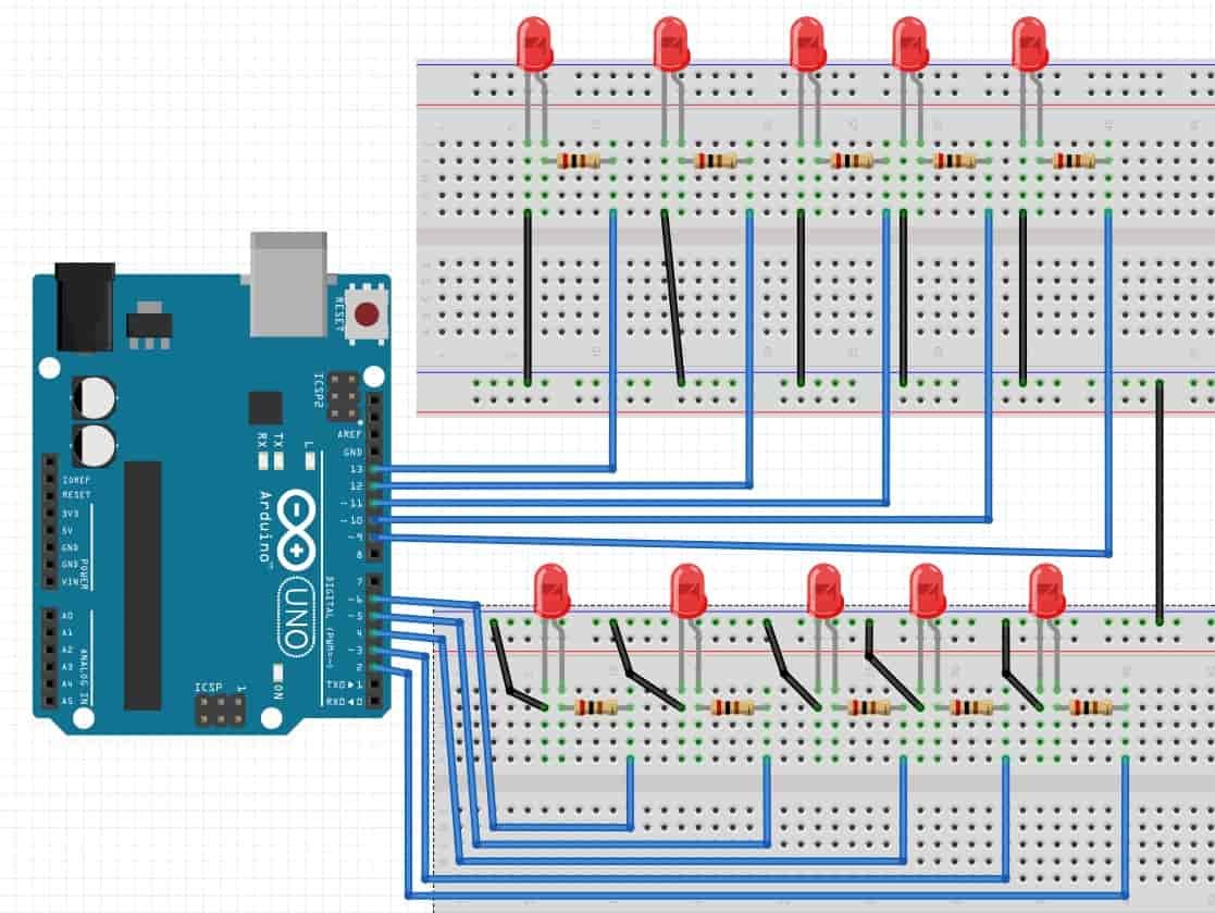
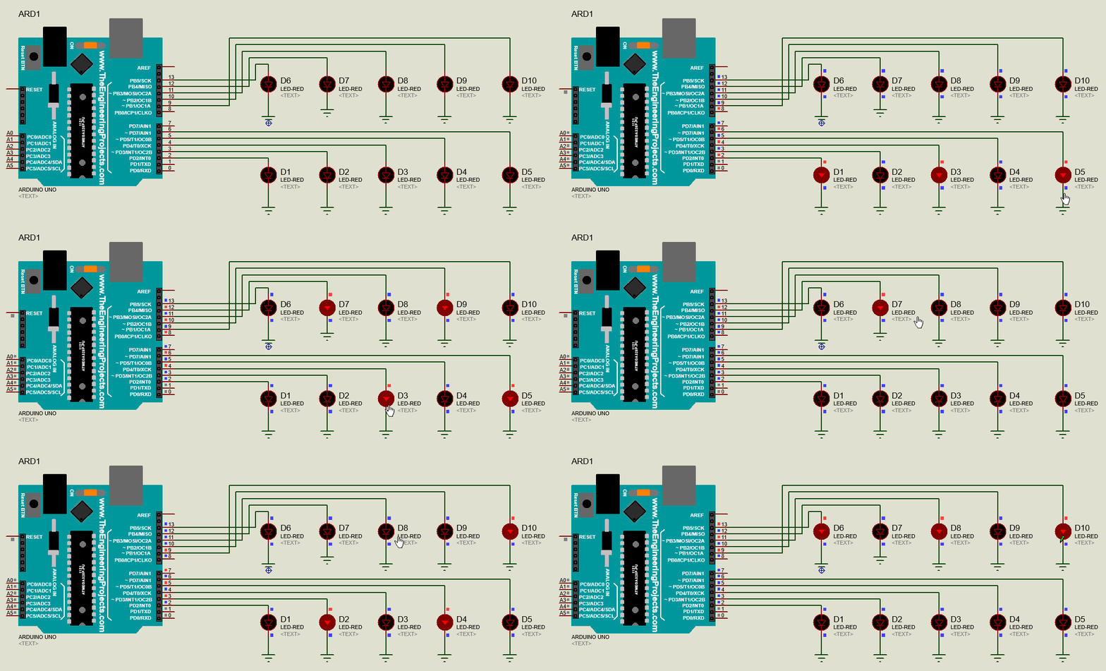
In this example, we will turn on and turn off even and odd LEDs that are connected with digital pins 2 to 13 of the Arduino. This code first turns on odd LEDs that are odd pin numbers such as 3, 5, 7, 9 and 11. After that, odd pin numbers will become logic low sequentially and LEDs will also turn off. After that, it will make even number digital pins logical high such as 2, 4, 6, 8,10 and similarly turn off LEDs. The delay of one second is used between each LED control.

Arduino Sketch
int del=1000; // variable define the delay
void setup()
{
 // make pins 2, 3, 4 and up to 13 as digital output pins
 //Instead of initializing individually, we make use of for loop
 // to initialize all pins
 for(int i=2; i<=13; i++)
  {
    pinMode(i,OUTPUT); // declare pins as a output
  }

}

void loop()
{
  // this for loop makes an odd number of digital output pins
  // digital high
  for(int i=2; i<=13; i++)
  {
  if(i%2==0)
  {digitalWrite(i,HIGH);
  delay(del);
  }
}
// this for loop makes an odd number of digital output pins
// digital low
for(int i=2; i<=13; i++)
{
  digitalWrite(i,LOW);
  delay(del);
}
// this for loop makes an even number of digital output pins
// digital high
for(int i=2; i<=13; i++)
{
  if(i%2!=0)
  {digitalWrite(i,HIGH);
  delay(del);
  }
}
// this for loop makes an even number of digital output pins
// digital low
for(int i=2; i<=13; i++)
{
  digitalWrite(i,LOW);
  delay(del);
}
}
Program Output
As you can see from the output of the circuit, first odd LEDs turns on one by one and then they turn off one by one. After that even number of digital output pins turn on and then they turn off one by one.

Read this next tutorial: Push Button Interfacing with Arduino
You may also like to read:
- 16×2 LCD Interfacing with Arduino – Explained with Example Codes
- Measure Analog voltage using Arduino ADC
- Interface HC-SR501 PIR Sensor with Arduino
- Joystick Based Servo Motor Control using Arduino
- Arduino Send Sensor Readings to Android app with MIT App Inventor
- I2C Communication Between Two Arduino Boards
- MAX30100 Pulse Oximeter and Heart Rate Sensor with Arduino


Thanks for the tutorial. It explained the procedure and codes well. But my question is how to get Arduinoin Proteus I use version 7
you can add library of arduino in proteus just download library of arduino in proteus and add in proteus models and library folder
in this project how many ohm ressistor do you use
Sir if were using arduino to control lights how the principle is working as the light bulb used here is not smart so how arduino is communicating with the normal bulb
Please could you tell me how to make the LED blink a specific Number of times.
and help me with the Arduino code
Thank you
thanks for sharing awesome info , you article was excellent and informative it very helpful