Automatic transfer switch for a generator: In this project, you will learn about the most commonly used circuit for automatic transfer switches in small power generators. There are many automatic transfer switches available in the market, ranging from expensive to cheap. The price difference is due to the type of technology used. Two types of automatic transfer switches can be found: analog electronics-based and digital electronics-based.
Analog electronics-based transfer switches utilize analog electronics components such as operational amplifiers, comparators, transistors, diodes, and mechanical relays. However, they do not include a digital display. On the other hand, digital automatic transfer switches are more commonly used nowadays. They utilize liquid crystal digital displays to show current and voltage values to the user. Additionally, they indicate the status of the AC main power and generator, indicating which power source is currently feeding the load. You can incorporate as many functionalities as needed. Here are some examples:
- Monitoring current and voltage values
- Indicating the status of the AC main power and generator
- Providing real-time information to the user
In this project, I will discuss a digital automatic transfer switch and give you a brief idea about its circuit diagram and programming. I will discuss the following things?
- What is an automatic transfer switch for a generator?
- Main components
- Circuit diagram
- How to write code for an automatic transfer switch?
What are Automatic Transfer Switches?
As its name suggests, an automatic transfer switch transfers the load from one power source to another in electrical terms. In this project, we use an automatic transfer switch to transfer the load between the AC main power and the generator in case either power source fails. We use automatic transfer switches for generators to automatically turn on the generator when the main power source is not available. We also use them to transfer the load to the generator after the generator’s transient period. The block diagram below illustrates an automatic transfer switch.
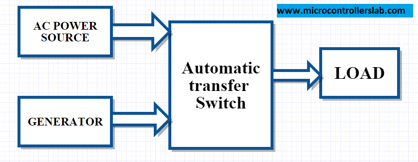
The above block diagram is self-explanatory, but if you still do not feel comfortable, let me know with your comments.
Automatic transfer switches main components
Automatic transfer switches (ATS) have several main components that work together to ensure seamless transfer of power between different sources. These components include:
Measurement of the AC voltage from the main AC power supply from Wapda and the output of Generator A is used to sense whether the AC supply from Wapda is available or not. You should possess knowledge about how to measure alternating voltage with the assistance of a microcontroller. If you are not familiar with how to measure AC voltage using a microcontroller, please refer to the following article:
- The microcontroller measures AC voltages from the AC main power source and the generator. It takes necessary actions based on the availability or non-availability of either source. It also displays digital values of voltage and current on a liquid crystal display.
- A liquid crystal display is used to digitally display current and voltage values. It also shows the status of both sources.
- Relays transfer from one source to another based on actions performed by a microcontroller, subject to the availability of sources.
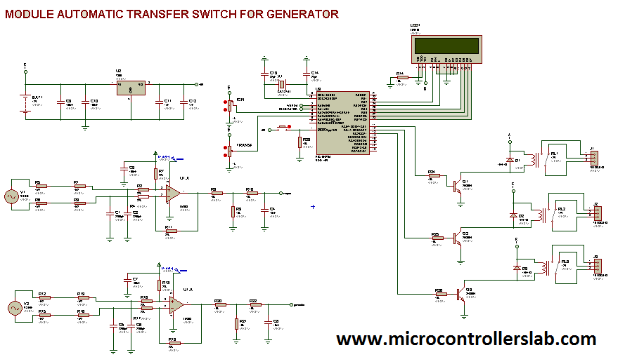
Circuit Diagram
The circuit diagram of ATS using a PIC microcontroller is shown below. We have used a PIC microcontroller to measure voltage and to take necessary actions on relays.
The PIC microcontroller continuously monitors the utility power parameters using the AC voltage measurement sensors. If it detects a voltage drop, frequency deviation, or other anomalies indicating a power outage or instability, it triggers the relay to switch to the generator power source. The microcontroller also monitors the utility power restoration. Once the utility power stabilizes and meets the predefined criteria, the ATS switches back to the utility power.
Additionally, the system can include safety features, such as delay mechanisms to avoid rapid switching, and a manual override to allow manual control in specific situations. The LCD display and user interface elements provide valuable feedback to the user, indicating the current power source and any relevant information.
This ATS setup improves the reliability of backup power systems, ensuring a quick and automated response to power interruptions, which is crucial for applications where uninterrupted power is essential, such as data centers, hospitals, or critical infrastructure.
Hire us to write firmware for you, contact us at: microcontrollerslabhub@gmail.com
Conclusion
In conclusion, an automatic transfer switch is an essential component in small power generators to ensure a seamless transfer of load between the AC main power and the generator. It allows for the automatic activation of the generator in the event of a power failure and transfers the load to the generator after the transient period. The most commonly used type of automatic transfer switch is the digital electronics-based switch, which incorporates functionalities such as monitoring current and voltage values and providing real-time information to the user through a digital display. By utilizing main components like microcontrollers, liquid crystal displays, and relays, the automatic transfer switch system improves the reliability of backup power systems, making it indispensable for critical applications like data centers and hospitals. Overall, understanding the concept, components, and circuit diagram of an automatic transfer switch is crucial for engineers and technicians involved in power management and backup systems.
You may also like to read:
Hello Bilal
Thank for this good post.
Could you please give a little explanation about the variable resistors connected to the PIC and about the role of the third relay because I think that two relays are sufficient to switch between the AC power and the generator, aren’t they?
I think that the role of the third relay is to connect the load to the generator after the stabilisation delay, is that correct?
hi
how far did you get with the articles and has this circuit been built and tested
thanks
yes it is tested circuit
hi
i downloaded the circuit diagram from your link and get a .DSN file which i am struggling to open
can you tell me what software i need to open the file
thanks
circuit diagram is design in proteus
hi
i have opened the file in proteus
when is press simulate i get the following errors
no modules J1 – J3
when i press the button in the schematic nothing happens
can you tell me what i am doing wrong as proteus is new to me i am used to using Diptrace
thanks
it is schematic diagram of ATS. You can purchase the code from shop
microcontrollerslabhub@gmail.com
Please send the complete code and circuit to me…. Kuleks4luv@yahoo.com
Project description
Please I need information and a circuit diagram for Automatic changeover switch with wireless generator control abilities or mechanism.
The generator rating is going to be between 2.2kva up to 2.5kva, and must be an automatic embedded systems generator on its own not the manual gen set.. Single phase generator and the Mains will be single phase too.. Ie 220volts 50hz…..
The system will be designed to select between two available source of power Givin preference or priority to one out of the two sources of power.
In this case, the selection is between public supply Mains and generator.
The ATS should monitor the Mains supply and check for complete failure or power outage upon which it changes the load over to the generator supply, sends command to the generator wirelessly to start ie ON.. And when the public supply is restored the ATS detects this sends an OFF command to the generator wirelessly to shut down.
check your email
please can u send me the complete code and schematic diagram or circuit drawing my email is oluwoleoluwatoyin6@gmail.com
contact me at microcontrollerslabhub@gmail.com
tank you very much i have got so money knowledge about different projects but i am electrical power engineering instructer , so i want to do some projects on my specialization. please help me if you have project related to my specialization.
Pleas I’m working on Automatic change-over switch with fuel level detector,using micro controller. could you please guide me on how the micro-controller works in the circuit.
you can avail my project service by contacting me at microcontrollerslabhub@gmail.com
Thank you for this idea Mr Bilal Malik
Dear Bilal Malik,
I am working on “GSM based backup generator monitoring using pic16877A and SIM300” including
* Fualt detection (Commercial power failure, breaker trip etc.
*Generator status (Auto, manual, running…
*Fuel level, running hours…
THANK YOU FOR ALL OF YOUR CONSIDERATION !!!
contact me at microcontrollerslabhub@gmail.com if you need my project assistance
plz bilal snd me ats code on pic control;er
on this id\
sajidhaidershigrieltr@yahoo.com
thank you for your effort
We want you program
Email
X-boy_smart@hotmail.com
Plz send me Code & circuit diagram :
mshehzad.uet@gmail.com
Thanks.
I need ATS circuitdiagram ATS in proteus with complete cote working in proteus,
may u send me for practice,
I m 70 ears old and jobless so i sit in home and passing time without any business
Thankyou
ABdul Majeed Tahir
Hola señor bilal soy nuevo en el forum me gustaría si usted puede mandarme el diagrama completo del diagrama de circuito de interruptor de transferencia automática del generador o en que pagina lo puedo descargar porque en el sitio donde esta publicado no se ve bien el diagrama del circuito .. ATT Cesar serrano.
Mr. Bilal could you guide me how are you cutting off generator ignition? or pls guide me about its mechanism.
through relay and microcontroller signal
From where are you sensing microcontroller signal and could you tell me about three relay what they are doing?
Please send me microcontroller code at szacpp@gmail.com.
Oh you mean relay cuts ignition when generator turns on? am i right?
yes
by sensing main power supply and code is not free of cost.
Ok…will It sense when generator stables at 220v or will sense at low voltage?
these features can be included
You mean when generator produces excat 220v then microcontroller will sense and during generator stablization ignition continously turns on. so the output: flywheel tooth will be spoil.
please tell me code price.
please i need the code
HI MY BOSS, I REALLY APPRECIATE YOUR POSTING MAY GOD CONTINUE TO OPEN WAY FOR YOU AND KNOWLEDGE.
Bhai how can i get the code and remaining explaination?
Thanks
Please send me the circuit diagram and code on this email
umer_muhammad52@yahoo.com
ok! I am final year of last graduating electrical power engineering . I want to do the project on automatic transfer switch , please send the design and simulation of ATS.
Please help me on design and simulation of automatic transfer switch
HI! BILAL
thank you for posting this different projects. now I am graduating class of 2018 by electrical power engineering. so I want to do project on ” automatic transfer switch design and simulation ”. for this if you have any source or document on simulation part please send for me . our last presentation will held on February 29/2018 G.C so please please help me by complete simulation of the circuit of automatic transfer switch .
I wait you as you will send within this week on my site dinkisadebela68@gmail.com
thank you
Hi Bilal
Could you please let me know if this system is sending a start and stop pulse to generator or it is just transfering the switch. Can we implement start and stop pulse with a required duration.
I need your help, My email ID is dkaul78@gmail.com
IRegards
Deepak
Thank you sir for your help…
Hello Bilal
Would you please send me schmatic and part values.
Thanks
Hi, thanks for your post. I’m studying electronic and I was finding this kind of project. Can you help me, with the price or how I can get diagram and code.