The CD4047 IC is a low power CMOS logic based multivibrator circuit IC. It can operate either in the monostable or astable mode. Furthermore, this IC is easy to configure for both modes and requires few external components to operate. It has a voltage range of 3V-15V but works best at 5V.
CD4047 Pinout Diagram
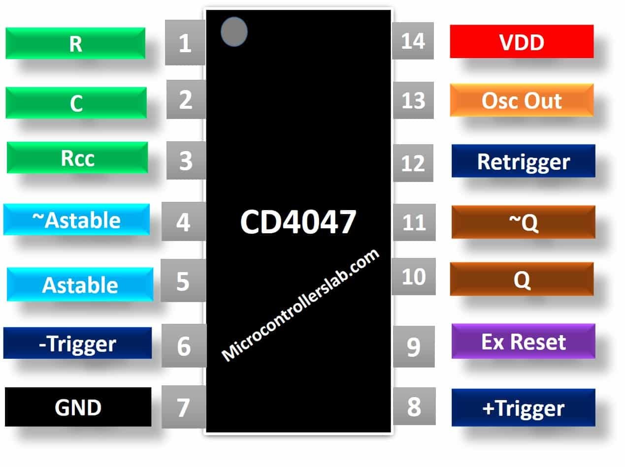
This CD4047 monostable/Astable multivibrator pinout has 14 pins. The pinout is the same for all packages. Three output pins provide PWM outputs such as Q, ~Q, and Osc_out. We can depict the working of each from the pinout diagram. For details and functions of each pin, check the next section.
Pin Configuration Description
It is a low gate IC having three outputs. It requires very few external components for performing astable or monostable multivibrator operation.
| Pin No. | Pin Name | Description |
|---|---|---|
| 1 | Cap timing (C) | Connect External Capacitors to this pin between Res timing and Rcc. |
| 2 | Res timing (R) | Connect External resistor to this pin between Cap timing and Rcc. |
| 3 | RC common (RCC) | This is a common terminal point between Rc and C |
| 4 | ~Astable | The LOW signal level at this input enables the Astable operation. |
| 5 | Astable | The HIGH signal level at this input enables the Astable operation. |
| 6 | -Trigger | Monostable operation enables when the signal at this input is triggers by high to low transition. |
| 7 | Vss | Ground of the circuit |
| 8 | +Trigger | Monostable operation is enabled when the signal at this input is triggered by low to high transition. |
| 9 | External Reset | When the reset input connects with the HIGH level, it resets the output Q to 0 and the non-inverting output to 1. |
| 10 | Q | Non-inverting output |
| 11 | ~Q | Inverting Output |
| 12 | Retrigger | Used to trigger pin 7 and pin 8 pins simultaneously in monostable mode |
| 13 | OSC Output | It gives oscillated output in astable mode. |
| 14 | Vdd | Positive power supply |
CD4047 Features
- Operate in both Monostable and Astable operation
- Require only a few external components that are one resistor and one capacitor
- Symmetrical buffered output characteristics
- High Noise Immunity
Monostable Mode Features
- Positive and negative edge trigger pins for enabling monostable operation.
- The output pulse width is independent of the trigger pulse duration.
- Retrigger pin is available for expansion of pulse width.
Astable Mode Features
- Creates a 50% duty cycle
- Free running operating mode with oscillated output
- Impressive frequency stability
Where to use CD4047?
You can use this IC in designing low power square wave inverters. It can operate in a monostable mode. Monostable can be used in signal conditioning or time delay circuits. This IC is an ideal choice for frequency Division and time Delay applications due to its complemented buffered outputs. One drawback of this IC has a 50% duty cycle of astable output, and you can’t change it.
Alternative Options
How to use CD4047?
Multivibrators are devices that change the state of electrical signals on either a regular basis or according to the requirement. CD4047 is also a multivibrator IC. It can operate in two modes. A capacitor is connected externally between pins 1 and 3 to determine the pulse width of the output signal in the monostable mode and the output frequency is determined in astable mode by connecting a resistor between pins 2 and 3. A reset input is provided to reset the output of Q to 0 and the other output will become 1.
Monostable Mode of Operation
The two inputs +trigger and -trigger are used to enable the monostable mode of operation. On applying +trigger input pin with low to high transition pulse and -trigger with high to low transition, the monostable output is obtained. The frequency of the outputs Q and ~Q can be calculated by the following formula:
f = 1/(8.8xRxC)
For example, if R=560K ohm and C=10nF, Frequency will be equal to:
f = 1/(8.8x560000x0.00000001)
The retrigger input is used to retrigger the device by trigging this input and +trigger input with low to high transition.
- To select, monostable mode, connect Astable pin with the ground and ~astable pin with 5 volts.
- The diagram shown below indicates the behavior of CD4042 IC in monostable mode.
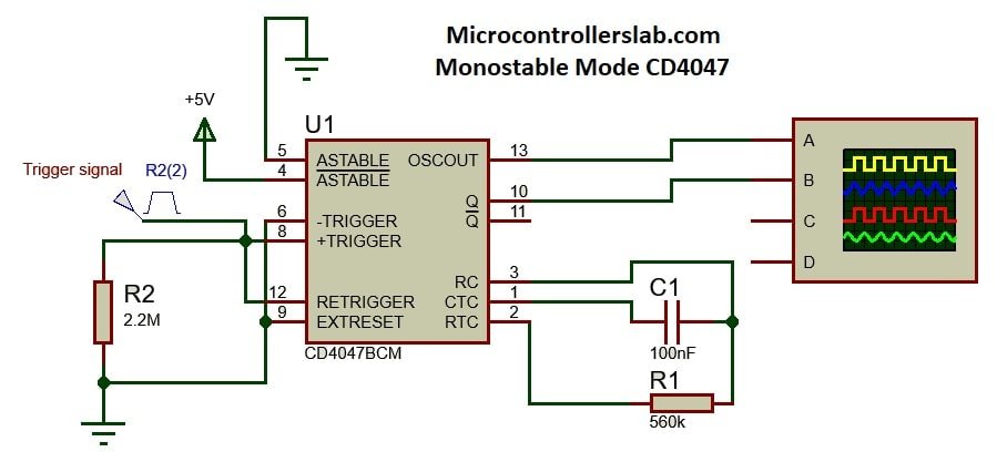
In CD4047 monostable mode, we get output in the PWM form on the osc_out pin. Q output pin remains active high and ~Q active low.

Astable Mode of Operation
The astable and ~astable inputs of CD4047 enable this mode of operation. The astable input connects with a high level. we can do it by applying low level on input ~astable, the IC operates in an astable mode. The output frequency can be calculated through timing components and is given by the following equation:
f= 1/ 4.4xRxC
In astable mode, we have an additional oscillator output. The timing diagram of the three outputs is shown below:

The oscillator output at pin 13 is of the *basic frequency. The Q output frequency is half to that of the basic frequency. Pin 11 output is the same as that of pin 10. But the output signal is inverted to 180 degrees. The time required to generate pulses is given by the formula:
t = 2.48×R×C

Example Circuits
In this section, we will see some practical example circuits using CD4047 multivibrator circuit IC.
Square wave generator using CD4047
We should use 4047 IC in astable mode to generate a square wave. A square wave is a PWM signal with equal width of logic high and low signal. We only need a couple of resistors and capacitors with this multivibrator IC to generate a square signal. This is a circuit diagram for the square PWM generator. We use RV1 as a variable resistor to get the variable frequency. This circuit shows a complete circuit diagram with an output signal.

100-watt Square Wave Inverter Circuit

CD4047 Applications
This IC is normally used for the conversion of DC signal to AC signal. Some of its applications are:
- Frequency division, multiplication, and discriminators
- Timing circuits and Timing delay applications
- Envelope Detection
DataSheet
Other Electronics Components:
- TC7660 Charge Pump DC-to-DC Voltage Converter
- 74HCT04 Hex Inverter IC
- TM1637- Grove 4 Digit Display Module
- CD4012 Dual Four Input NAND Gate IC
- CD4066 CMOS Quad Bilateral Switches IC
- RC522 RFID Reader Module
- How to use TL494 pulse width modulation control IC
- Introduction to IRF3205
- ADC0804 ADC introduction, pinout, features and examples
- L293D Motor Driver IC introduction, pinouts and how to use
- ULN2003 introduction, pinout, example and features
- Max232 IC pinout, features, pins description, and example
- CD4008 4-Bit Full ADDER IC
- DAC0832 8-BIT DIGITAL TO ANALOG CONVERTER IC
- 74LS138 – 3 TO 8 LINE DECODER IC
- LM4871 Audio Power Amplifier Pinout, Examples and Applications