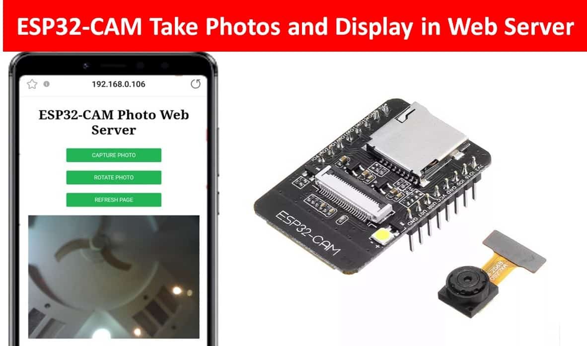
In this project, we will create an ESP32-CAM Photo Web Server. The Web server will present the user with three options: to capture a photo, rotate the photo, and refresh the page. After capturing the photo, the photo will get saved in the ESP32-CAM’s SPIFFS files and will be fetched from the filesystem. The web server will display the current image after the user presses the refresh button. Moreover, image rotation functionality is also provided on the webserver.
You can also read this getting started guide on ESP32 CAM:
- ESP32 CAM Video Streaming and Face Recognition with Arduino IDE
- ESP32-CAM AI-Thinker Board – All about GPIO Pins
ESP32-CAM Photo Web Server Project Overview
We aim to build a webpage through which the user will be able to capture a photo via the ESP32-CAM which then gets displayed in the web server along with an option to rotate it as well.
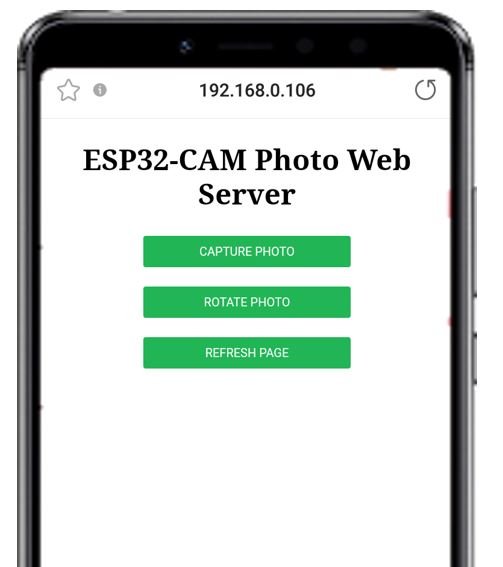
The web server will consist of a title: “ESP32-CAM Photo Web Server” and three buttons.
The first button will be for capturing the photo. When the user will click this button, the ESP32-CAM will capture the image in front of its lens and save it to SPIFFS. A few moments will take for the image to get captured and saved onto the SPIFFS successfully.
The second button will allow the user to rotate the latest image which is displayed on the web server. The rotations will be 90 degrees clockwise.
The third button is to refresh the web page. This will refresh the web page and display the current photo saved on the ESP32-CAM SPIFFS.

Connecting ESP32-CAM with FTDI programmer
We will require the following components for this project:
- ESP32-CAM development board
- FTDI Programmer/ USB Serial to TTL Converter
- Connecting Wires
- External 5V power supply (optional)
Unlike the ESP32 development board, the ESP32-CAM does not come with the USB port attached to it. So to upload a program sketch to the ESP32-CAM, we will need to use an FTDI programmer (USB to TTL Serial converter).
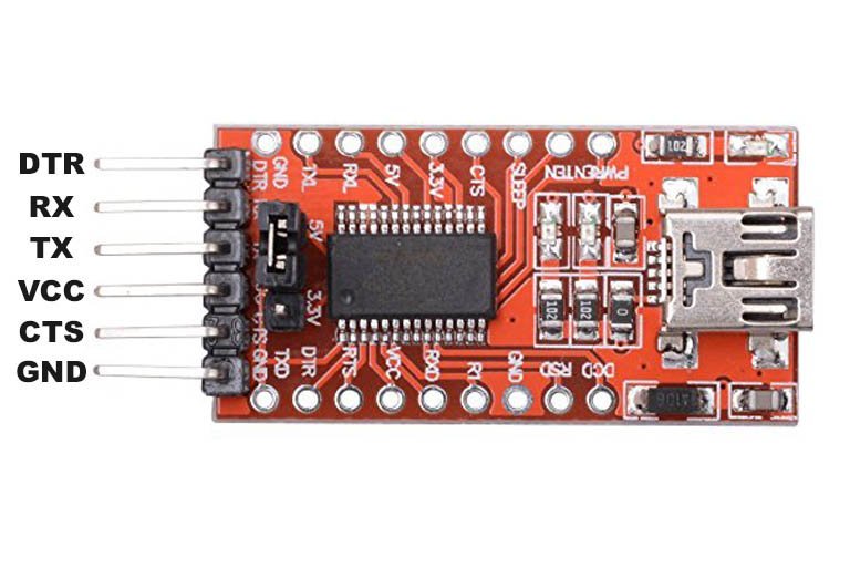
You can learn more about this FTDI cable here:
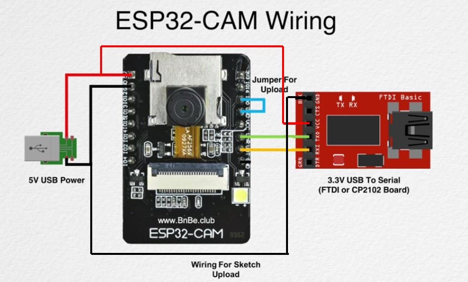
The table shows the connections between the ESP32-CAM and FTDI programmer:
| ESP32-CAM | FTDI Programmer |
| 5V | VCC |
| UOR (GPIO3) | TX |
| UOT (GPIO1) | RX |
| GND | GND |
Connect the 5V pin of ESP32-CAM with the VCC pin of the FTDI programmer to power up. Both grounds of the two devices will be connected in common. The TX pin of the FTDI programmer will be connected with UOR (GPIO3) of ESP32-CAM. Likewise, the RX pin will be connected with the UOT (GPIO1) of the ESP32-CAM module.
Additionally, you will need to connect GPIO0 with GND to enable the ESP32-CAM module to go in flashing mode. Remove this connection after uploading the program sketch to the module.
On some ESP32-CAM boards, you will get a brown-out detector error which is due to the insufficient voltage provided by the FTDI cable. In that case, you should connect an external 5V power supply to ESP32 as shown below:
Setting up Arduino IDE for ESP32-CAM Photo Web Server
We will use Arduino IDE to program our ESP32 development board. Thus, you should have the latest version of Arduino IDE. Additionally, you also need to install the ESP32 plugin. You can visit the link shown below to have a look.
Installing Libraries
We will need the following libraries to build our web server.
- ESPAsyncWebServer library
- AsyncTCP library
The ESPAsyncWebServer library will help us in creating our web server easily. With this library, we will set up an asynchronous web server. AsyncTCP library will also be incorporated as it a dependency for the ESPAsyncWebServer library. These two libraries are not available in the Arduino library manager. Therefore, we will have to download and load them on our ESP32-CAM board ourselves.
- To install the ESPAsyncWebServer library for free, click here to download. You will download the library as a .zip folder which you will extract and rename as ‘ESPAsyncWebServer.’ Then, transfer this folder to the installation library folder in your Arduino IDE.
- To install the Async TCP library for free, click here to download. You will download the library as a .zip folder which you will extract and rename as ‘AsyncTCP.’ Then, transfer this folder to the installation library folder in your Arduino IDE.
Likewise, you can also go to Sketch > Include Library > Add .zip Library inside the IDE to add the libraries as well.
After installation of the libraries, restart your IDE.
ESP32-CAM Photo Web Server Arduino Sketch
Open your Arduino IDE and go to File > New. A new file will open. Copy the code given below in that file and save it.
Remember to replace the network credentials.
#include "WiFi.h"
#include "esp_camera.h"
#include "esp_timer.h"
#include "img_converters.h"
#include "Arduino.h"
#include "soc/soc.h"
#include "soc/rtc_cntl_reg.h"
#include "driver/rtc_io.h"
#include <ESPAsyncWebServer.h>
#include <StringArray.h>
#include <SPIFFS.h>
#include <FS.h>


const char* ssid = "YOUR_SSID";
const char* password = "YOUR_PASSWORD";


AsyncWebServer server(80);

boolean new_photo = false;

#define photo_path "/image.jpg"

// OV2640 camera module pins (CAMERA_MODEL_AI_THINKER)
#define PWDN_GPIO_NUM     32
#define RESET_GPIO_NUM    -1
#define XCLK_GPIO_NUM      0
#define SIOD_GPIO_NUM     26
#define SIOC_GPIO_NUM     27
#define Y9_GPIO_NUM       35
#define Y8_GPIO_NUM       34
#define Y7_GPIO_NUM       39
#define Y6_GPIO_NUM       36
#define Y5_GPIO_NUM       21
#define Y4_GPIO_NUM       19
#define Y3_GPIO_NUM       18
#define Y2_GPIO_NUM        5
#define VSYNC_GPIO_NUM    25
#define HREF_GPIO_NUM     23
#define PCLK_GPIO_NUM     22

const char index_html[] PROGMEM = R"rawliteral(
<!DOCTYPE HTML><html>
<head>
  <meta name="viewport" content="width=device-width, initial-scale=1">
  <style>
    body { text-align:center; }
    .vert { margin-bottom: 10%; }
    .hori{ margin-bottom: 0%; }
    button {
  background-color: #21b555;
  border: none;
  padding: 7px 10px;
  text-align: center;
  font-size: 10px;
  border-radius: 2px;
  width: 50%;
  color: white;
}
  </style>
</head>
<body>
  <div id="container">
    <h2>ESP32-CAM Photo Web Server</h2>
      <p><button onclick="capturePhoto()">CAPTURE PHOTO</button></p>
      <p><button onclick="rotatePhoto();">ROTATE PHOTO</button></p>
      <p><button onclick="location.reload();">REFRESH PAGE</button></p>
  </div>
  <div><img src="saved-photo" id="photo" width="90%"></div>
</body>
<script>
  var deg = 0;
  function capturePhoto() {
    var xhr = new XMLHttpRequest();
    xhr.open('GET', "/capture", true);
    xhr.send();
  }
  function rotatePhoto() {
    var img = document.getElementById("photo");
    deg += 90;
    if(isOdd(deg/90)){ document.getElementById("container").className = "vert"; }
    else{ document.getElementById("container").className = "hori"; }
    img.style.transform = "rotate(" + deg + "deg)";
  }
  function isOdd(n) { return Math.abs(n % 2) == 1; }
</script>
</html>)rawliteral";

void setup() {
  Serial.begin(115200);

  WiFi.begin(ssid, password);
  while (WiFi.status() != WL_CONNECTED) {
    delay(1000);
    Serial.println("Connecting to WiFi...");
  }
  if (!SPIFFS.begin(true)) {
    Serial.println("An Error has occurred while mounting SPIFFS");
    ESP.restart();
  }
  else {
    delay(500);
    Serial.println("SPIFFS mounted successfully");
  }

  Serial.print("IP Address: ");
  Serial.println(WiFi.localIP());

  // Turn-off the 'brownout detector'
  WRITE_PERI_REG(RTC_CNTL_BROWN_OUT_REG, 0);

  // OV2640 camera module
  camera_config_t config;
  config.ledc_channel = LEDC_CHANNEL_0;
  config.ledc_timer = LEDC_TIMER_0;
  config.pin_d0 = Y2_GPIO_NUM;
  config.pin_d1 = Y3_GPIO_NUM;
  config.pin_d2 = Y4_GPIO_NUM;
  config.pin_d3 = Y5_GPIO_NUM;
  config.pin_d4 = Y6_GPIO_NUM;
  config.pin_d5 = Y7_GPIO_NUM;
  config.pin_d6 = Y8_GPIO_NUM;
  config.pin_d7 = Y9_GPIO_NUM;
  config.pin_xclk = XCLK_GPIO_NUM;
  config.pin_pclk = PCLK_GPIO_NUM;
  config.pin_vsync = VSYNC_GPIO_NUM;
  config.pin_href = HREF_GPIO_NUM;
  config.pin_sscb_sda = SIOD_GPIO_NUM;
  config.pin_sscb_scl = SIOC_GPIO_NUM;
  config.pin_pwdn = PWDN_GPIO_NUM;
  config.pin_reset = RESET_GPIO_NUM;
  config.xclk_freq_hz = 20000000;
  config.pixel_format = PIXFORMAT_JPEG;

  if (psramFound()) {
    config.frame_size = FRAMESIZE_UXGA;
    config.jpeg_quality = 10;
    config.fb_count = 2;
  } else {
    config.frame_size = FRAMESIZE_SVGA;
    config.jpeg_quality = 12;
    config.fb_count = 1;
  }
  esp_err_t err = esp_camera_init(&config);
  if (err != ESP_OK) {
    Serial.printf("Camera init failed with error 0x%x", err);
    ESP.restart();
  }

  server.on("/", HTTP_GET, [](AsyncWebServerRequest * request) {
    request->send_P(200, "text/html", index_html);
  });

  server.on("/capture", HTTP_GET, [](AsyncWebServerRequest * request) {
    new_photo = true;
    request->send_P(200, "text/plain", "Capturing Photo using ESP32-CAM");
  });

  server.on("/saved-photo", HTTP_GET, [](AsyncWebServerRequest * request) {
    request->send(SPIFFS, photo_path, "image/jpg", false);
  });


  server.begin();

}

void loop() {
  if (new_photo) {
    captureSave_photo();
    new_photo = false;
  }
  delay(1);
}

// Check if photo capture was successful
bool check_photo( fs::FS &fs ) {
  File f_pic = fs.open( photo_path );
  unsigned int pic_sz = f_pic.size();
  return ( pic_sz > 100 );
}

// Capture Photo and Save it to SPIFFS
void captureSave_photo( void ) {
  camera_fb_t * fb = NULL;
  bool ok = 0;

  do {
    Serial.println("ESP32-CAMP capturing photo...");

    fb = esp_camera_fb_get();
    if (!fb) {
      Serial.println("Failed");
      return;
    }

    Serial.printf("Picture file name: %s\n", photo_path);
    File file = SPIFFS.open(photo_path, FILE_WRITE);
    if (!file) {
      Serial.println("Failed to open file in writing mode");
    }
    else {
      file.write(fb->buf, fb->len);
      Serial.print("The picture has been saved in ");
      Serial.print(photo_path);
      Serial.print(" - Size: ");
      Serial.print(file.size());
      Serial.println(" bytes");
    }
    file.close();
    esp_camera_fb_return(fb);

    ok = check_photo(SPIFFS);
  } while ( !ok );
}
How the Code Works?
We will start off by including all the necessary libraries required for this project.
#include "WiFi.h"
#include "esp_camera.h"
#include "esp_timer.h"
#include "img_converters.h"
#include "Arduino.h"
#include "soc/soc.h"
#include "soc/rtc_cntl_reg.h"
#include "driver/rtc_io.h"
#include <ESPAsyncWebServer.h>
#include <StringArray.h>
#include <SPIFFS.h>
#include <FS.h>
Next, we will create two global variables, one for the SSID and another for the password. These will hold our network credentials which will be used to connect to our wireless router. Replace both of them with your network credentials to ensure a successful connection.
const char* ssid = "YOUR_SSID";
const char* password = "YOUR_PASSWORD";
The AsyncWebServer object will be used to set up the ESP32-CAM web server. We will pass the default HTTP port which is 80, as the input to the constructor. This will be the port where the server will listen to the requests.
AsyncWebServer server(80);We will define a Boolean variable called ‘new_photo’ and set it as false. This will be used later on in the code to check if a new photo is captured.
boolean new_photo = false;Moreover, we will also define photo path with its name for the photo to get saved on the ESP32 SPIFFS.
#define photo_path "/image.jpg"The following definitions are for OV2640 camera module pins. We are using CAMERA_MODEL_AI_THINKER.
#define PWDN_GPIO_NUM     32
#define RESET_GPIO_NUM    -1
#define XCLK_GPIO_NUM      0
#define SIOD_GPIO_NUM     26
#define SIOC_GPIO_NUM     27
#define Y9_GPIO_NUM       35
#define Y8_GPIO_NUM       34
#define Y7_GPIO_NUM       39
#define Y6_GPIO_NUM       36
#define Y5_GPIO_NUM       21
#define Y4_GPIO_NUM       19
#define Y3_GPIO_NUM       18
#define Y2_GPIO_NUM        5
#define VSYNC_GPIO_NUM    25
#define HREF_GPIO_NUM     23
#define PCLK_GPIO_NUM     22
Creating the Web Page
We will create an index_html variable to store all the HTML, CSS, and Javascript text which will be required to build our web page.
We will create a meta tag to make sure our web server is available for all browsers e.g., smartphones, laptops, computers etc.
<meta name="viewport" content="width=device-width, initial-scale=1">CSS styling
Inside the index_html variable we have the <style></style> tags which mark the beginning and end of the CSS styling file.
We will set the display text in the centre of the webpage. For the buttons, the font size, font colour and positioning will be is specified.
  <style>
    body { text-align:center; }
    .vert { margin-bottom: 10%; }
    .hori{ margin-bottom: 0%; }
    button {
  background-color: #21b555;
  border: none;
  padding: 7px 10px;
  text-align: center;
  font-size: 10px;
  border-radius: 2px;
  width: 50%;
  color: white;
}
  </style>
Defining HTML
The next step will be to define the HTML web page body. This will go inside the <body></body> tags which mark the beginning and the ending of the script. This part will include the heading of the web page and the buttons.
We will include the heading of our webpage inside the <h2></h2> tags and it will be ‘ESP32-CAM Photo Web Server’. You can use any other heading as you prefer.
<h2>ESP32-CAM Photo Web Server</h2>Next three buttons will be created. We will define the button inside <button></button> tags.
The first button displays the text ‘CAPTURE PHOTO’. When this button is clicked the capturePhoto() function will be called. The ESP32-CAM captures a photo then.
The second button displays the text ‘ROTATE PHOTO.’ When clicked, the rotatePhoto() function will be called. The current photo displayed in the web server will get rotated.
The third button displays the text ‘REFRESH PAGE.’ When this button is clicked, location.reload() is called. This will refresh the web page and display the current photo.
 <p><button onclick="capturePhoto()">CAPTURE PHOTO</button></p>
 <p><button onclick="rotatePhoto();">ROTATE PHOTO</button></p>
 <p><button onclick="location.reload();">REFRESH PAGE</button></p>
The current image will be displayed after the three buttons, with a set width of 90%.
<div><img src="saved-photo" id="photo" width="90%"></div>JavaScript
Inside the <script></script> tags, we will include the JavaScript to handle the Web page.
We will define the capturePhoto() function. This is the JavaScript function which we will be called when the ‘CAPTURE PHOTO’ button will be clicked and create a HTTP GET request on the /capture URL.
  function capturePhoto() {
    var xhr = new XMLHttpRequest();
    xhr.open('GET', "/capture", true);
    xhr.send();
  }
Inside this function we use the XMLHttpRequest. This will allow us to make an HTTP request in JavaScript. To make the HTTP GET request to we will follow three steps:
Firstly, we will create an XMLHttpRequest as follows:
var xhr = new XMLHttpRequest();Secondly, we will initialize the request by using the xhr.open() method. Inside it we will pass on three arguments. The first argument specifies the type of HTTP method which is GET in our case. The second argument is the URL (/capture) to which are board will request upon. The last argument is true which specifies that the request is asynchronous.
xhr.open('GET', "/capture", true);Lastly, we will use xhr.send() to open the connection. Our server will now be able to receive the HTTP GET request whenever the user will interact with the button.
xhr.send();The next function that we will define is rotatePhoto(). This will be called when the ‘ROTATE PHOTO’ button will be clicked. It will be responsible to rotate the picture by 90 degrees.
  function rotatePhoto() {
    var img = document.getElementById("photo");
    deg += 90;
    if(isOdd(deg/90)){ document.getElementById("container").className = "vert"; }
    else{ document.getElementById("container").className = "hori"; }
    img.style.transform = "rotate(" + deg + "deg)";
  }
setup()
Inside the setup() function, we will open a serial connection at a baud rate of 115200.
Serial.begin(115200);The following section of code will connect our ESP32-CAM board with the local network whose network credentials we already specified above. We will use the WiFi.begin() function. The arguments will be the SSID and the password which we defined earlier in the code. After a successful connection is established, the IP address gets displayed on the serial monitor. We will use this IP address to access our web server. SPIFFS will also get initialized and if there is error in the initialization then the ESP board will be restarted.
  WiFi.begin(ssid, password);
  while (WiFi.status() != WL_CONNECTED) {
    delay(1000);
    Serial.println("Connecting to WiFi...");
  }
  if (!SPIFFS.begin(true)) {
    Serial.println("An Error has occurred while mounting SPIFFS");
    ESP.restart();
  }
  else {
    delay(500);
    Serial.println("SPIFFS mounted successfully");
  }

  Serial.print("IP Address: ");
  Serial.println(WiFi.localIP());
The following code sets the OV2640 camera module and the settings required for the photo capturing.
  // Turn-off the 'brownout detector'
  WRITE_PERI_REG(RTC_CNTL_BROWN_OUT_REG, 0);

  // OV2640 camera module
  camera_config_t config;
  config.ledc_channel = LEDC_CHANNEL_0;
  config.ledc_timer = LEDC_TIMER_0;
  config.pin_d0 = Y2_GPIO_NUM;
  config.pin_d1 = Y3_GPIO_NUM;
  config.pin_d2 = Y4_GPIO_NUM;
  config.pin_d3 = Y5_GPIO_NUM;
  config.pin_d4 = Y6_GPIO_NUM;
  config.pin_d5 = Y7_GPIO_NUM;
  config.pin_d6 = Y8_GPIO_NUM;
  config.pin_d7 = Y9_GPIO_NUM;
  config.pin_xclk = XCLK_GPIO_NUM;
  config.pin_pclk = PCLK_GPIO_NUM;
  config.pin_vsync = VSYNC_GPIO_NUM;
  config.pin_href = HREF_GPIO_NUM;
  config.pin_sscb_sda = SIOD_GPIO_NUM;
  config.pin_sscb_scl = SIOC_GPIO_NUM;
  config.pin_pwdn = PWDN_GPIO_NUM;
  config.pin_reset = RESET_GPIO_NUM;
  config.xclk_freq_hz = 20000000;
  config.pixel_format = PIXFORMAT_JPEG;

  if (psramFound()) {
    config.frame_size = FRAMESIZE_UXGA;
    config.jpeg_quality = 10;
    config.fb_count = 2;
  } else {
    config.frame_size = FRAMESIZE_SVGA;
    config.jpeg_quality = 12;
    config.fb_count = 1;
  }
Initializing ESP32-CAM:
  esp_err_t err = esp_camera_init(&config);
  if (err != ESP_OK) {
    Serial.printf("Camera init failed with error 0x%x", err);
    ESP.restart();
  }
Server Handling Requests
In this section, we will discuss how our ESP32-CAM board will handle the requests on the different URLs.
/root URL
Firstly, we will deal with the /root URL request which the ESP32-CAM board will receive.
We will use the send_P() method. The handling function will respond to the client by using the send_P() method on the request object. This method will take in three parameters. The first is 200 which is the HTTP status code for ‘ok’. The second is “text/html” which will correspond to the content type of the response. The third is the text saved on the index_html variable which will be sent.
  server.on("/", HTTP_GET, [](AsyncWebServerRequest * request) {
    request->send_P(200, "text/html", index_html);
  });
/capture URL
Now we will deal with the /capture URL request. This will be received by the board when the ‘CAPTURE PHOTO’ button will be clicked. It will set the boolean variable ‘new_photo’ to true and respond to the client by using the send_P() method on the request object. This method will take in three parameters. The first is 200 which is the HTTP status code for ‘ok’. The second is “text/plain” which will correspond to the content type of the response. The third is the text that will be sent.
  server.on("/capture", HTTP_GET, [](AsyncWebServerRequest * request) {
    new_photo = true;
    request->send_P(200, "text/plain", "Capturing Photo using ESP32-CAM");
  });
/saved-photo
Now we will deal with the /saved-photo URL request. This will be received by the board when the ‘REFRESH PAGE’ button will be clicked. It will respond to the client by using the send() method on the request object. This method will take in four parameters. The current photo saved as ‘image/jpg’ saved on the SPIFFS will be sent to the client.
  server.on("/saved-photo", HTTP_GET, [](AsyncWebServerRequest * request) {
    request->send(SPIFFS, photo_path, "image/jpg", false);
  });
To start the server, we will call begin() on our server object.
server.begin();loop()
Inside the loop() function we will check if the capture photo is button is clicked then call the captureSave_photo() function and set the ‘new_photo’ variable back to false. The captureSave_photo() will be used to capture the photo by the ESP32-CAM and then save it on the SPIFFS filesysytem.
void loop() {
  if (new_photo) {
    captureSave_photo();
    new_photo = false;
  }
  delay(1);
}
Capturing Photo and saving on SPIFFS
The check_photo() function returns true if a valid picture got saved on the SPIFFS. This is achieved by opening the file on the photo path specified and checking its size.
bool check_photo( fs::FS &fs ) {
  File f_pic = fs.open( photo_path );
  unsigned int pic_sz = f_pic.size();
  return ( pic_sz > 100 );
}
The captureSave_photo() function is responsible to capture the photo and then save it on the SPIFFS on the photo path specified.
void captureSave_photo( void ) {
  camera_fb_t * fb = NULL;
  bool ok = 0;

  do {
    Serial.println("ESP32-CAMP capturing photo...");

    fb = esp_camera_fb_get();
    if (!fb) {
      Serial.println("Failed");
      return;
    }

    Serial.printf("Picture file name: %s\n", photo_path);
    File file = SPIFFS.open(photo_path, FILE_WRITE);
    if (!file) {
      Serial.println("Failed to open file in writing mode");
    }
    else {
      file.write(fb->buf, fb->len);
      Serial.print("The picture has been saved in ");
      Serial.print(photo_path);
      Serial.print(" - Size: ");
      Serial.print(file.size());
      Serial.println(" bytes");
    }
    file.close();
    esp_camera_fb_return(fb);

    ok = check_photo(SPIFFS);
  } while ( !ok );
}
ESP32 CAM Web Server Demo
Now, we are ready to compile and upload the code to our ESP32-CAM. Make sure the FTDI programmer is properly connected with the module and GPIO0 is grounded as well.
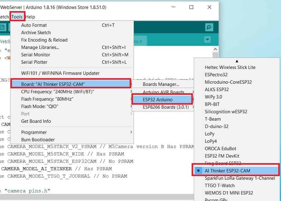
Choose the correct board and COM port before uploading your code to the ESP32-CAM board. Go to Tools > Board and select ESP32 AI Thinker.
Next, go to Tools > Port and select the appropriate port through which your board is connected.
Click on the upload button to upload the code into the ESP32-CAM board.
If you view Connecting….._____….._____….. in the error window, press the RESET button present on the ESP32-CAM as shown below:

After you have successfully uploaded your code to the board, remove the connecting wire from GPIO0 and GND.
Now open the serial monitor and press the RESET button on the ESP32-CAM.
You will be able to view the following messages including the IP address:

Open a web browser and type this IP address. Press enter. The web page will open.
Now click the CAPTURE PHOTO button to take a photo. After a few moments, press the REFRESH PAGE button. The image will get displayed.
Press the ROTATE PHOTO button to rotate the image according to your needs.

You may also like to read: