In this user guide, we will learn to interface MS5611 barometric pressure sensor module with ESP8266 NodeMCU. Firstly, we will introduce you to the MS5611 sensor including its pinout, features, and interfacing with ESP8266. Secondly, we will install the Arduino MS5611 library in Arduino IDE to access the sensor data. Lastly, we see two examples to display temperature and pressure values on a serial monitor and on the SSD1306 OLED display.
We have similar guides for ESP32 and Arduino Uno:
- Interface MS5611 Barometric Pressure Sensor with ESP32
- Interface MS5611 Barometric Pressure Sensor with Arduino
MS5611 Sensor Module Introduction
The MS5611 barometric pressure sensor module comes in a compact user-friendly size that features the MS6611 chip from MEAS Switzerland. This chip in fact measures the barometric pressure with an absolute accuracy of ±1.5 mbar within the range of 450-1100 mbar. As a whole, the sensor is able to measure pressure readings in the range of 10-1200 mbar. Moreover, the MS5611 sensor also features an on-chip temperature sensor that measures the die temperature within the range of -40˚C to +85˚C with a good accuracy of ±0.8˚C.
The MS5611 sensor module features a 3.3V precise voltage regulator and level translator. Therefore, it is very convenient to use with a microcontroller such as Arduino, ESP8266, STM32 etc. Due to its low power, compact size and inexpensive nature, the MS5611 sensor is a great choice to be used with microcontrollers for barometric pressure and altimeter measurements. Moreover, due to its low power consumption (less than 1.4mA for measuring sensor data and less than 0.15µA when in standby mode) it is very suitable to use in devices that use a battery.

I2C and SPI Interfaces
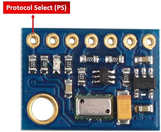
The MS561 sensor module supports both I2C and SPI communication protocols to transmit sensor data to the microcontroller. To select the type of interface, the Protocol Select pin also known as PS is used. When this pin is in a high state (through a 1k pull-up resistor) the selected interface is I2C and when the state of this pin is low then the selected interface is SPI. The I2C communication protocol is selected by default which means that the I2C/SPI protocol selection pin is held high.
I2C Interface
By default, the MS561 sensor module uses I2C communication protocol to transmit sensor data to the microcontroller. The sensor module features the SCL (serial clock) and SDA (serial data) pins which connect with the I2C interface of ESP8266 or other sensors supporting the same interface.
One interesting thing to note here is that, the MS561 sensor module comes with two I2C addresses which are 0x77 and 0x76. By default, the I2C address is set as 0x77. The user can change the I2C address through the I2C Address Selection Pin also known as CSB.

The CSN pin consists of an internal 2.2k ohm pull-down resistor which ensures that when this pin is unconnected (low state), the I2C address is 0x77 (default). Whereas, when the state of this pin is set high then the I2C address is 0x76. This address changing feature gives the users the liberty to use multiple MS5611 sensor modules on the same bus by setting the same I2C address for each sensor.
SPI Interface
As mentioned previously, the MS5611 sensor module also supports the SPI communication protocol. This interface is enabled when the Protocol Select pin is set to a low state (connected to ground).
MS5611 Sensor Module Pinout
The following figure shows the pinout diagram of MS5611 sensor module. The MS5611 sensor module consists of seven pins.
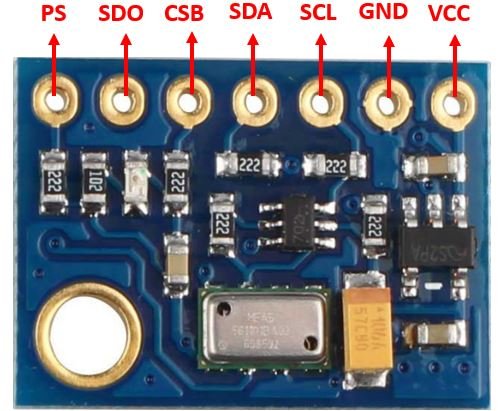
The following lists the pinout of the MS5611 sensor module and their brief description.
| MS5611 Module Pin | Description |
|---|---|
| VCC | This is the pin that supplies power to the sensor module in the range 3.3-5.5V. Connect it with 3.3V pin of ESP8266. |
| GND | This is the ground pin for providing the common ground between the devices. |
| SCL | This is the serial clock pin which generates the clock signal. It is used in both I2C and SPI interfaces. |
| SDA | This is the serial data pin which is used to send and receive data. It is used in both I2C and SPI interfaces. |
| CSB | This is the chip select pin. It is used in both I2C and SPI interfaces. |
| SDO | This is the serial data out pin which is used in SPI interface. |
| PS | This is the protocol select pin. |
Interface MS5611 Module with ESP8266
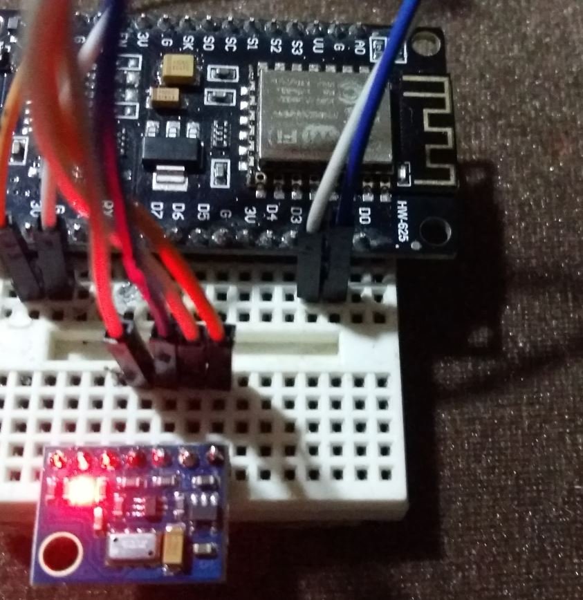
In this section, let us show you how to connect the MS5611 sensor module with ESP8266.
You will need the following components
- ESP8266 NodeMCU board
- MS5611 Sensor Module
- Jumper wires
We will connect the MS5611 sensor module with ESP32 using the I2C interface and program our board accordingly. The connection of MS5611 with the ESP32 board is super simple. Connect the VCC terminal of MS5611 module with 3.3V of ESP8266, ground with the ground (common ground), SCL of the sensor with SCL pin of ESP8266, and SDA of the sensor with the SDA pin of ESP8266.
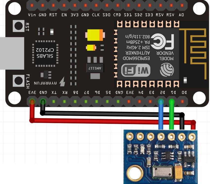
For ESP8266, the default I2C pins for SDA are GPIO4 and for SCL are GPIO5. The connections between the two devices can be seen in the table below.
| ESP8266 | MS5611 Module |
|---|---|
| 3.3V | Vin |
| GPIO4 (D2) | SDA |
| GPIO5 (D1) | SCL |
| GND | GND |
Follow the schematic diagram below for ESP8266 and the sensor module and connect them accordingly.
Install MS5611 Arduino Library
Before we proceed further, you should make sure that you have the latest version of Arduino IDE installed on your system. Moreover, you should also install an ESP8266 add-on in Arduino IDE. If your IDE does not have the plugin installed you can visit the link below:
Installing ESP8266 library in Arduino IDE and upload code
As we are connecting the MS5611 sensor module with ESP8266, therefore, we will have to install the libraries to access the sensor data. We will require one library for this project:
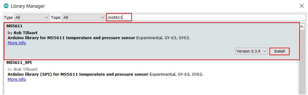
- MS5611 by Rob Tillaart
We will use the Library Manager in our Arduino IDE to install the latest versions of the libraries. Open your Arduino IDE and go to Sketch > Include Libraries > Manage Libraries. Type MS5611 in the search bar and install the latest version of the library by Rob Tillaart.
Arduino Code – Get MS5611 Readings on Arduino Serial Monitor
This sketch displays the temperature and pressure readings on Arduino serial monitor after every second.
#include "MS5611.h"

MS5611 MS5611(0x77);

void setup() {
  Serial.begin(115200);
  while(!Serial);

  if (!MS5611.begin()) {
    Serial.println("MS5611 not found, check wiring!");
    while (1);
  }
}

void loop() {
  MS5611.read();
  Serial.print("Temperature °C = ");
  float temp = MS5611.getTemperature();
  Serial.print(temp, 2);
  Serial.print("\tPressure mb = ");
  float pressure = MS5611.getPressure();
  Serial.print(pressure, 2);
  Serial.println();
  delay(1000);
}
How the Code Works?
Now, let us understand how each part of the code works.
The code starts with including the necessary libraries which are needed for the proper functionality of the code. The MS5611.h library will enable us to initialize and read the MS5611 sensor using the I2C communication protocol.
#include "MS5611.h"Next we create the MS5611 object using the I2C address.
MS5611 MS5611(0x77);setup()
Inside the setup() function, we start the serial communication at a baud rate of 115200 and then initialize the MS5611 sensor. If the sensor initialization is not a success, a relevant message will be printed on the serial monitor.
void setup() {
  Serial.begin(115200);
  while(!Serial);

  if (!MS5611.begin()) {
    Serial.println("MS5611 not found, check wiring!");
    while (1);
  }
}
loop()
Inside the loop() function, the ESP8266 first obtains the MS5611 sensor readings after every second and stores them in their respective float variables, ‘temp’ for temperature and ‘pressure’ for pressure. Temperature readings are acquired through MS5611.getTemperature(). Pressure readings are accessed using the MS5611.getPressure() function. These readings are then printed on the serial terminal.
void loop() {
  MS5611.read();
  Serial.print("Temperature °C = ");
  float temp = MS5611.getTemperature();
  Serial.print(temp, 2);
  Serial.print("\tPressure mb = ");
  float pressure = MS5611.getPressure();
  Serial.print(pressure, 2);
  Serial.println();
  delay(1000);
}
Demonstration
To see the demonstration of the above code, upload the code to the ESP8266 connected with the OLED. Choose the correct board and COM port. Go to Tools > Board and select NodeMCU 1.0. Next, go to Tools > Port and select the appropriate port through which your board is connected.

Click on the upload button to upload the code into the ESP8266 board. After you have uploaded your code to the board press its RST button.

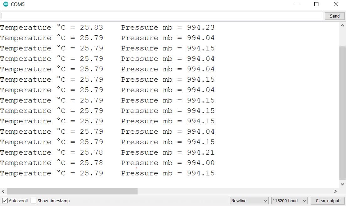
In your Arduino IDE, open up the serial monitor and set the baud rate to 115200. The serial monitor will start displaying the temperature and pressure readings along with the units. New readings will be displayed after every second.
Display MS5611 Sensor values on OLED Display
In this section, we will see how to display the MS5611 sensor readings on a 0.96 SSD1306 OLED display using Arduino IDE and ESP8266.
Installing SSD1306 OLED Library in Arduino IDE
To use the OLED display in our project, we have to install the Adafruit SSD 1306 library in Arduino IDE. Follow the steps below to successfully install it.
Open Arduino IDE and click on Sketch > Library > Manage Libraries. The following window will open up.

Type ‘SSD1306’ in the search tab and install the Adafruit SSD1306 OLED library.

Schematic – OLED with ESP8266 and MS5611 Sensor Module
You will need the following components
- ESP8266 NodeMCU board
- MS5611 Sensor Module
- SSD1306 OLED
- Breadboard
- Jumper wires
The table below shows the terminals of the three devices which should be connected together.
| OLED Display | ESP8266 | MS5611 Sensor Module |
|---|---|---|
| VCC | 3.3V | VCC |
| GND | GND | GND |
| SCL | GPIO5 (D1) | SCL |
| SDA | GPIO4 (D2) | SDA |
Assemble the circuit as shown in the schematic diagram below:
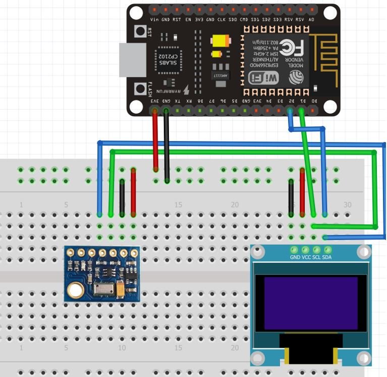
As you can see above, we have connected all the VCC terminals with 3.3V pin of ESP8266. The SCL terminals are connected with D1 and the SDA terminals are connected with D2. The grounds are also common.
Arduino Sketch to Display MS5611 Readings on OLED
Copy the following code to your Arduino IDE and upload it to ESP8266 after assembling the above circuit diagram.
#include "MS5611.h"
#include <Adafruit_GFX.h>
#include <Adafruit_SSD1306.h>

MS5611 MS5611(0x77);
Adafruit_SSD1306 display = Adafruit_SSD1306(128, 64, &Wire, -1);

void setup() {
  Serial.begin(115200);
  while(!Serial);

  if (!MS5611.begin()) {
    Serial.println("MS5611 not found, check wiring!");
    while (1);
  }

  display.begin(SSD1306_SWITCHCAPVCC, 0x3C);
   // init done
  display.display();
  delay(100);
  display.clearDisplay();
  display.display();
  display.setTextColor(WHITE);
}

void loop() {
  MS5611.read();
  Serial.print("Temperature: ");
  float temp = MS5611.getTemperature();
  Serial.print(temp, 2);
  Serial.print("\tPressure: ");
  float pressure = MS5611.getPressure();
  Serial.print(pressure, 2);
  Serial.println();

  display.setCursor(0,0);
  display.clearDisplay();

  display.setTextSize(1);
  display.setCursor(0,0);
  display.print("Temperature: ");
  display.setTextSize(2);
  display.setCursor(0,10);
  display.print(temp);
  display.print(" ");
  display.setTextSize(1);
  display.cp437(true);
  display.write(167);
  display.setTextSize(2);
  display.print("C");

  // display humidity
  display.setTextSize(1);
  display.setCursor(0, 35);
  display.print("Pressure: ");
  display.setTextSize(2);
  display.setCursor(0, 45);
  display.print(pressure);
  display.print(" mb");

  display.display();
  delay(1000);
}
How the Code Works?
The maximum portion of the code is the same as we have discussed earlier except for the OLED display part. Therefore, we will only explain the OLED display part here.
We will first include all the required libraries for the MS5611 sensor as well as the OLED display which we just installed before.
#include "MS5611.h"
#include <Adafruit_GFX.h>
#include <Adafruit_SSD1306.h>
Now, we will create another object named ‘display’ which will be handling the OLED display. Also, define the size of the OLED display by passing arguments to the Adafruit_SSD1306() function.
Adafruit_SSD1306 display = Adafruit_SSD1306(128, 64, &Wire, -1);Initialize the OLED display by calling the begin() method on the display object.
display.begin(SSD1306_SWITCHCAPVCC, 0x3C); Next, we will clear the OLED screen by calling clearDisplay() function. Also, we set the color of the text using setTextColor() function and pass WHITE as an argument. If we have a dark background, we will display our text in white and if we have a bright background then we will display the text in black.
  display.clearDisplay();
  display.display();
  display.setTextColor(WHITE);
Display Readings on the OLED
Inside the loop() function, we obtain the MS5611 sensor readings and print them on the OLED display.
We display the temperature and pressure values on the serial monitor on the OLED one by one. This block of code displays MS5611 sensor values on OLED and updates the values after every 1 second.
  display.setCursor(0,0);
  display.clearDisplay();

  display.setTextSize(1);
  display.setCursor(0,0);
  display.print("Temperature: ");
  display.setTextSize(2);
  display.setCursor(0,10);
  display.print(temp);
  display.print(" ");
  display.setTextSize(1);
  display.cp437(true);
  display.write(167);
  display.setTextSize(2);
  display.print("C");

  // display humidity
  display.setTextSize(1);
  display.setCursor(0, 35);
  display.print("Pressure: ");
  display.setTextSize(2);
  display.setCursor(0, 45);
  display.print(pressure);
  display.print(" mb");

  display.display();
  delay(1000);
In the above code, the setTextSize() function is used to set the size of the font. We used low size for simple text such as “Temperature” and “Pressure” and high size font to display actual temperature and pressure readings. We will use the setCursor() function to denote the x and the y-axis position from where the text should start. Finally, the print() function writes the text on the defined position.
Demonstration
To see the demonstration of the above code, upload the code to ESP8266. But, before uploading code, make sure to select the board from Tools > Board and also select the correct COM port to which the board is connected from Tools > Port.
Once the code is successfully uploaded to the board, the OLED will start displaying the readings.
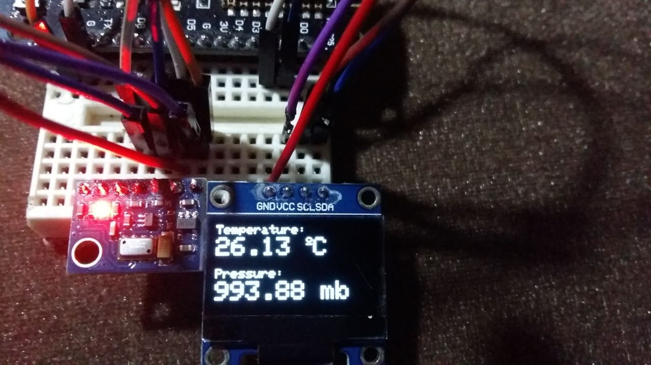
video demo:
You may also like to read:
- ESP8266 NodeMCU with SHT31 Temperature & Humidity Sensor
- ESP8266 NodeMCU with HTU21D Temperature and Humidity Sensor
- ESP8266 with BMP180 Atmospheric Pressure and Temperature sensor
- Display Sensor Readings in Gauges with ESP8266 Web Server
- MAX30102 Pulse Oximeter and Heart Rate Sensor with ESP8266
- MLX90614 Non-contact Infrared Temperature Sensor with ESP8266
- K-Type Thermocouple MAX6675 Amplifier with ESP8266 NodeMCU
- NEO-6M GPS Module with ESP8266 NodeMCU and Track Location on Google Maps