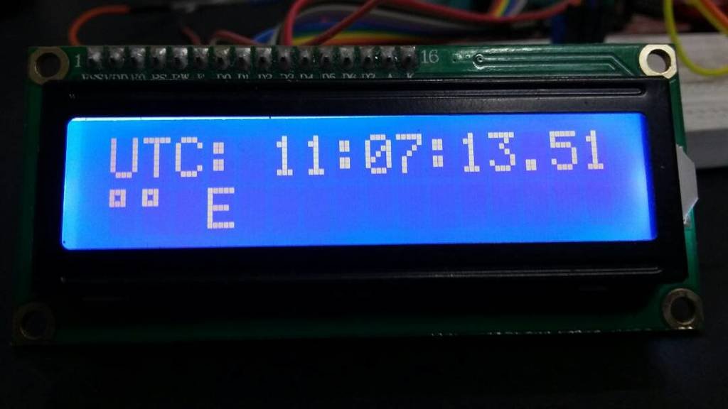
GPS based clock using pic microcontroller : This project is about how to design a GPS based clock using pic microcontroller and how to make a universal clock using pic18f452 microcontroller. First of all we will see what is GPS based universal digital clock and what are it applications. GPS based clock can be used to make universal digital clock with provides current time according to your location unlike traditional watches where you have to adjust time manually when you go from one region to another. This clock can adjust it time automatically according to your position with the help of GPS module.
How GPS based clock works?
There are many satellites available in our space which can be used to get your ordinates like latitude, amplitude, date and time. I have already posted a article on how interface GPS module with pic microcontroller. In which I have explained how to get co ordinates of your current location from any available satellite. But satellite provides us complete information which includes latitude, amplitude, date and time. So we can get date and time from this information also.
How to design GPS based clock?
GPS has many application in vehicle tracking system, vehicle theft intimation system and GPS based data loggers. But GPS based clock can be used for many applications like military missions, railway station and bus stations and many other fields. GPS module can provide you data from more than 10 satellites but you can choose any satellite. In this project, I have used $GPGGA satellite to design digital clock. But you can use any other satellite if you want. But to do so you have to make changes in code. We will receive data from $GPGGA satellite in the form of string as shown below:
$GPGGA,001038.00,3334.2313457,N,11211.0576940,W,2,04,5.4,354.682,M,-26.574,M,7.0,0138*79
I will explain this string in later part of this article. I have used pic18F452 microcontroller to receive data from GPS receiver. Holux M-89 GPS module is used as a GPS receiver. whenever we turn on this module by supplying power to it, it will start getting data from all available satellites. Data received by GPS receiver will be available at transmit pin of GPS module. You can receive this data with pic microcontroller using serial communication. Date received is shown below:
As you can see it will receive data from all available satellites. But we have use only $GPGAA satellite to get time for GPS based clock. Data received by pic18f452 microcontroller from GPS receiver saves in a string and after that string is analyzed with the help of string functions to get time. Date received from $GPGAA satellite can be interrupted as below: 
As shown above after $GPGAA is time in UTC format. We can also extract longitude and latitude from this string.
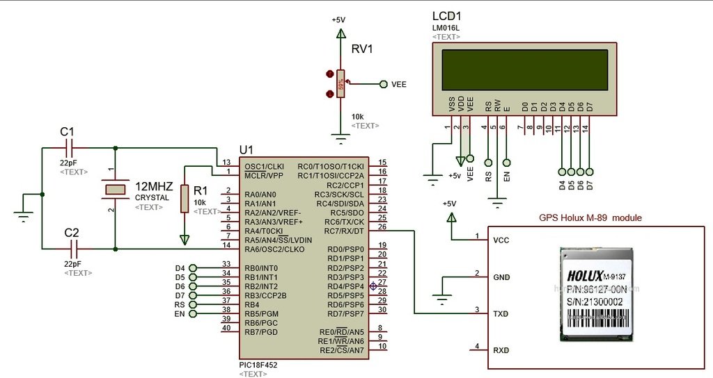
GPS based clock circuit diagram
Circuit diagram is given. It consists of 2*16 LCD , PIC18F452 microcontroller and GPS receiver. I have explained above the working and use of all these components except LCD. LCD is interfaced with pic microcontroller to display value of time in UTC format.
Code of GPS based clock
// LCD module connections
sbit LCD_RS at RB4_bit;
sbit LCD_EN at RB5_bit;
sbit LCD_D4 at RB0_bit;
sbit LCD_D5 at RB1_bit;
sbit LCD_D6 at RB2_bit;
sbit LCD_D7 at RB3_bit;

sbit LCD_RS_Direction at TRISB4_bit;
sbit LCD_EN_Direction at TRISB5_bit;
sbit LCD_D4_Direction at TRISB0_bit;
sbit LCD_D5_Direction at TRISB1_bit;
sbit LCD_D6_Direction at TRISB2_bit;
sbit LCD_D7_Direction at TRISB3_bit;
// End LCD module connections
void GPS_GetDataAndDisplayIt(void)
{
char Temp = 0, Index = 0;
while(!UART1_Data_Ready());
Temp = UART1_Read();
if (Temp == '$')
{
while(!UART1_Data_Ready());
Temp = UART1_Read();
if (Temp == 'G')
{ while(!UART1_Data_Ready());
Temp = UART1_Read();
if (Temp == 'P')
{
while(!UART1_Data_Ready());
Temp = UART1_Read();
if (Temp == 'G')
{
while(!UART1_Data_Ready());
Temp = UART1_Read();
if (Temp == 'G')
{
while(!UART1_Data_Ready());
Temp = UART1_Read();
if (Temp == 'A')
{
while(!UART1_Data_Ready());
Temp = UART1_Read(); // skiping ','
while(!UART1_Data_Ready());
Temp = UART1_Read();
Lcd_Cmd (_LCD_THIRD_ROW);
Lcd_Out_Cp("UTC: "); // displaying UTC on LCD
while (Temp != ',')
{
Lcd_Chr_Cp(Temp); // Displaying Time on LCD
while(!UART1_Data_Ready());
Temp = UART1_Read();
Index ++;
if (Index == 2 || Index == 4)
Lcd_Chr_Cp(':');
}
Index = 0;
Lcd_Cmd (_LCD_FIRST_ROW);
Lcd_Out_Cp("LAT: "); // displaying Latitude data
while(!UART1_Data_Ready());
Temp = UART1_Read();
while (Temp != ',')
{
Lcd_Chr_Cp(Temp); // Displaying latitude on LCD
while(!UART1_Data_Ready());
Temp = UART1_Read();
Index ++;
if (Index == 2)
Lcd_Chr_Cp(223); // Displaying degree sign
}
Index = 0;
while(!UART1_Data_Ready());
Temp = UART1_Read();
Lcd_Chr_Cp(' ');
Lcd_Chr_Cp(Temp); // Displaying Direction on LCD
Lcd_Cmd (_LCD_SECOND_ROW);
Lcd_Out_Cp("LNG: "); // displaying Longitude
while(!UART1_Data_Ready());
Temp =UART1_Read();
while(!UART1_Data_Ready());
Temp = UART1_Read();
while (Temp != ',')
{
Lcd_Chr_Cp(Temp); // Displaying longi on LCD
while(!UART1_Data_Ready());
Temp = UART1_Read();
Index ++;
if (Index == 3)
Lcd_Chr_Cp(223); // Displaying degree sign
}
while(!UART1_Data_Ready());
Temp = UART1_Read();
Lcd_Chr_Cp(' ');
Lcd_Chr_Cp(Temp); // Displaying Direction on LCD

Lcd_Cmd (_LCD_FOURTH_ROW);
while(!UART1_Data_Ready());
Temp = UART1_Read(); // Skiping ','
Lcd_Out_Cp("Fix: "); // displaying Longitude
while(!UART1_Data_Ready());
Temp = UART1_Read();
Lcd_Chr_Cp(Temp); // Displaying fix value on LCD
while(!UART1_Data_Ready());
Temp = UART1_Read(); // Skiping ','
Lcd_Out_Cp(" No.SAT: "); // displaying Longitude
while(!UART1_Data_Ready());
Temp = UART1_Read();
while(Temp != ',')
{
Lcd_Chr_Cp(Temp); // Displaying No. of SATS
while(!UART1_Data_Ready());
Temp = UART1_Read();
}
Lcd_Chr_Cp(' ');
}

}

}

}

}
}

}
void main()
{
Lcd_Init(); // Initialize LCD
UART1_Init(9600); // Initialize UART module at 9600 bps
TRISB=0X00;
//ANSELH=0X00;
Delay_ms(100); // Wait for UART module to stabilize
Lcd_Cmd(_LCD_CLEAR); // Clear display
Lcd_Cmd(_LCD_CURSOR_OFF); // Cursor off
Lcd_Cmd (_LCD_FIRST_ROW);
Lcd_Out_Cp("GPS MODUE");
Lcd_Cmd (_LCD_SECOND_ROW);
Lcd_Out_Cp("DATA LOGGER");
Lcd_Cmd (_LCD_THIRD_ROW);
Lcd_Out_Cp("SD CARD");
Lcd_Cmd (_LCD_FOURTH_ROW);
Lcd_Out_Cp("BY BILAL");
Delay_ms(2000);
Lcd_Cmd(_LCD_CLEAR); // Clear display
while(1) {
GPS_GetDataAndDisplayIt();
}

}
Code for GPS based clock is written using mikro c for pic compiler. PIC18f452 microcontroller is use to received data from GPS receiver through UART serial communication. LCD is connected with PORTB of pic microcontroller to display time.


Thank you for sharing this wonderful project! It is what I have been researching. I have all the components. So, your code is what I needed.
I am very much a novice at coding. So, I have a few questions…
– Can Microchip’s IDE MPLab X compile your Micro C code? I have only worked in plain C and I know that will compile in MPLab X.
– Can your code run directly on a PIC18F4550? I use the 40 pin model. If not, do I need to do anything other than adjust the pin assignments? (Is the proper term “Port assignments?”) Here is the link for the PIC18F4550 Data Sheet: http://ww1.microchip.com/downloads/en/DeviceDoc/39632e.pdf
– Would you be able to help me see it through to completion? I would be glad to give you the final code to share, here.
Thank you for your help. I look forward to hearing from you.
Indoor use ?? Are you having trouble on power up of the clock
to get the first fix and get the clock time/date running ?
I know most GPS modules don’t like indoor use because
of the lack of ‘open sky reading’ ..
If not what are your suggestions about the GPS reception ?
Thanks !