NE556 is a dual timer IC which is used for creating time delays or oscillations. It is a dual version of the 555 timer IC. The two timers inside this chip share the common ground and power supply but operate independently. It can operate in the astable or the monostable mode by only two external components. One resistor and capacitor (RC) are connected externally for providing timing control
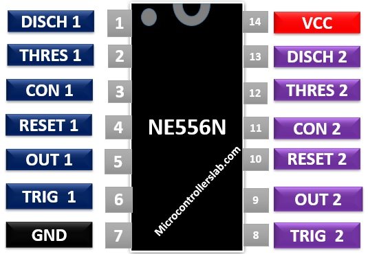
NE556 Pinout Diagram
This dual timer high precision IC has 14 pins. This pinout diagram shows the pin assignment.
Pin Configuration Description
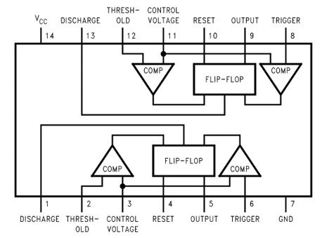
As it is a dual timer IC, therefore it has two timers namely A and B. The detailed description of pins of both timers is mentioned below:
Pin#01, 13: DISCHARGE A, B
It has two discharge pins as it is a dual timer IC. Connected this to voltage supply through a resistor and ground through a capacitor. It is used to discharge the capacitor. When the voltage at this pin reaches 2/3 of the voltage supply, it toggles the output signal from high to low.
Pin#02, 12: THRESHOLD A, B
It is active high input which is compared with the 2/3 of voltage supply value through a comparator integrated inside the chip. This input is used to set the flipflop.
Pin#03, 11: CONTROL A, B
This pin is used to adjust the threshold and trigger voltages. The voltage applied at this pin determines the pulse width by modulating the output signal. Normally, it is left disconnected. But, in case of noisy circuits, a capacitor of 0.01µF is connected at this pin whose other end is grounded.
Pin#04, 10: Reset A, B
This pin is used to reset or disable both timers. When it is applied with low or negative logic, it will reset all the inputs. If you don’t need this function, connect this pin with Vcc.
Pin#05, 09: OUTPUT A, B
It is the timer output pin.
Pin#06, 08: Trigger A, B
The output of the timer depends on this pin. It is responsible for changing the state of flipflop from set to reset.
Pin#07: Ground
Connect ground pin with ground terminal of power supply.
Pin#14: Vcc
Connect power supply at this pin.
NE556 Dual Timer Features
- A dual version of NE556 consisting of two precision timers which operate in both monostable and astable modes.
- It is specified for operation from 4.5 V to 16 V.
- TTL compatible output which can source or sink current of up to 150mA.
- Adjustable duty cycle.
- It can produce a timing delay from microseconds to hours.
- The operating temperature range is from 0 to 70 degrees Celsius.
- It has temperature stability better than 0.005% per ˚C.
Please check the datasheet given at the end for more information on specifications and features.
Alternative Dual Timer IC
- LM556
- CD4047
- 4048
- CD4538
Where to use it?
The NE556 IC is a modified form of NE555 chip. When you need two 555 timers, you can use this IC as it has two timers inside a single package. It is a highly stable timer IC that can be used for producing accurate time delays and oscillations.
How to use NE556?
This IC is used in two different modes which are mentioned above.
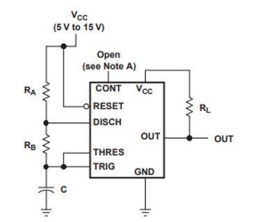
Astable Mode of operation
In astable mode, it is used as an oscillator to provide a continuous stream of rectangular pulses. It can also provide a pulsed sound of a specific frequency. The resistors RA and RB and a capacitor C are used to determine that specific frequency.
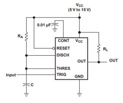
Circuit Monostable operation
The LM556 timer can also be used as a one-shot pulse generator by operating it in monostable mode. The pulse begins when the trigger input falls below 1/3 of Vcc. The flip flop is set and the output pulse is generated. The RA and C network is used to determine the width of the output pulse. When the capacitor voltage becomes equal to 2/3 of the supply voltage, it will reset the flipflop and pulse end. The width output pulse width can be set by adjusting the RA and C values. The reset input resets the outputs to zero and re-initiate a timing cycle.
Applications
This NE556 timer IC is used in:
- Pulse generation and Time Delay generation
- Precision timing
- Linear Ramp Generators
- Pulse width or pulse position modulation
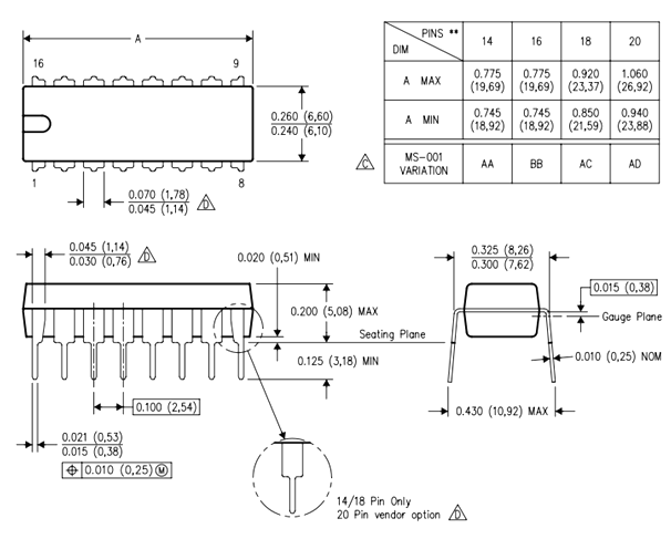
2D Diagram