Monochrome 0.96” OLED Display is the best small screen display in the market. However, this display uses OLED technology with SPI and I2C communication support to show the data. OLED doesn’t show the values/data on the screen with the use of the backlight. It uses its light by each pixel. Almost there is a total of 128×64 pixels on the screen. In Monochrome, the screen has only one color which depends on the OLED type. Its display is always in light and doesn’t require any contrast adjustment due to OLED technology. All the pixels are controllable through the SSD1306 driver. Every pixel and communication signal pass through the SSD1306.
What is OLED Display?
OLED stands for organic light-emitting diode. Its name shows that it is a flat light emitting technology that is developed when two organic thin films are connected in series between two electric conductors. When an electric current is supplied to these conductors then the organic compound is made which emits the bright light. Typically, one conductor is the transparent conductor between these two conductors therefore there is no need for any backlight to emits the light. Therefore, this OLED display has improved image quality, full viewing angle, high brightness, better contrast, wide color range, low power consumption, more efficient and reliable as compared to a simple LCD display. It is mainly used in digital display devices such as computer monitors, mobile phones, handheld games, and televisions screens, etc.
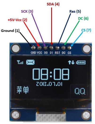
Monochrome 0.96” OLED Display Pinout Diagram
The pin configuration of the OLED is simple like others because of the driver. The basic input only gets to the driver and then the driver performs the rest of the functions. The OLED Display communication pins are of two types, one is SPI and the other is I2C. The OLED performs faster in SPI communication but it is popular with I2C communication. The reason for the popularity is the lower number of pins. All the Power and communication pins are:
Power Pins
| PINS | DETAILS | |
|---|---|---|
| Pin1 | GND | Connect the Pin1 with the ground pin to make the common ground for proper working. |
| Pin2 | Power (VCC, VDD, 5V) | OLED uses a single power pin for all the power inputs. |
Communication Pins
| PINS | DETAILS | |
|---|---|---|
| Pin3 | SCK (CLK, SCL) | The Pin3 will perform a common clock signal for both microcontroller/Arduino with OLED. In SPI and I2C communication, it will act as a clock pin. |
| Pin4 | SDA (MOSI, DI) | This pin will receive the data from the controlling device/Arduino. In OLED only “data” in should have to receive data, there won’t be any data output. So, the Pin4 will act as data input for both SPI and I2C. |
| Pin5 | RES (Reset, RST) | The reset pin will reset all the internal buffer of the OLED driver. |
| Pin6 | D/C (A0) | The Pin6 will change the data and command registers on the input requirements. |
| Pin7 | Chip Enable (CS, CE) | The Pin7 is an enable pin, which will activate the display on the LOW input signal. |
How to connect Pins with Microcontroller?
Every OLED display consists of seven pins which are used for different purposes. First one is GND pin which is connected with source ground for suppling ground to this display, second one is VCC pin which is connected with source VCC for suppling +5V to this display. Third one is SCK pin which is used as a lock pin or used for both 12C and SPI. Fourth one is SDA pin which is used as a data pin for module. Fifth one is RES pin means reset pin which is used for resetting to this OLED display. Sixth one is DC pin means data command pin and is used for SPI protocol. Similarly, the last one or seventh one is CS pin means chip select pin and is used when one or more modules are used under SPI protocol.
SSD1306 Monochrome 0.96 OLED Display Features
- The OLED display can view from every angle of the maximum 160 degrees.
- The display supports both 3v and 5v power, which makes it work with both 3.3V and 5V logic.
- The SSD1306 driver and its library make the OLED display the characters and bitmaps with simple commands.
- The different colors OLED is also available, even in different sizes are also available.
- The OLED display is smaller in size and has a better display as compared to LCD
Alternative Displays
- Nokia5110 LCD Module
- 2.4″ TFT LCD Display Module overview
- TFT Display
- TM1637- Grove 4 Digit Display Module
- 16×2 LCD Module – Liquid Crystal Display
- 7 Segment Display
Applications
- The small screen games use the OLED SSD1306.
- The OLED is also available in smartwatches too.
- The Display has multiple uses in consumer electronics.
Working Principle of OLED Display
The working principle of this OLED display is very simple. This LED display consists of organic material layers which are situated between two electrodes that are called anode and cathode. When these electrodes are connected to dc supply then current is passed through these electrodes then electrons are deposited on electrode substrate. Basically, organic material is made of semiconductor material whose electrical properties are in between conductor and semi-conductor. Therefore, when current is supplied to their electrodes then the electrons which are deposited at electrode substrate, delocalize the organic molecule.
During this delocalization the electron of organic molecule moves from valance band to conduction band. Similarly, the light is produce in this organic material layer. The most simple and basic OLED display consists of a single organic layer whose example is first light emitting device which was synthesized by J.H. For improving the efficiency of LED display device multilayer LED display could be made with the help of two or more layers of organic material. Similarly, for improving the conduction properties different material could be aid in electrode material.
OLED Display Construction
The OLED SSD1306 functionality is different from the LCD functionality. The OLED pixel generates its light by using multiple layers. There are almost 6 layers in each pixel of the OLED. The 2 layers are just the glass of the display which keeps the other layers in contact. The outer layers also protect them from the oxygen because it is too reactive to the atmosphere. The cathode and anode connect itself with the emissive layers and conductive. The emissive connects with the cathode and the conductive layer connects with anode the emissive layer receives the electron from the cathode and the conductive layer sends the electrons to the anode.
The basic operation here is, when the anode and cathode get the power then the emissive layer gets the electrons in a larger amount. Therefore, the conductive layer gets the hole due to the transfer of its electrons to the anode. Now Emissive layer has electrons availability in larger amount but the conductive layer has the electrons deficiency. Therefore, Now the electrons jump from the emissive layer to the conductive layer to fill the hole. This hole filling process releases a massive amount of energy. This energy shows the whole pixel in the form of light which makes the character/data display on the OLED with its own generated light. There are massive amounts of pixels on the display screen. To control every pixel a driver helps.
SSD1306 Monochrome 0.96 OLED Display Driver
The driver OLED uses is SSD1306. It controls the 128×64 pixels with simple serial communication pins. The OLED input pins are the input pins of the SSD1306 but the output pins are different from the input pins. Even they are larger in numbers as compare to the input pins. Most of the pins are the same in their functionality. Here’s the block diagram of the driver:
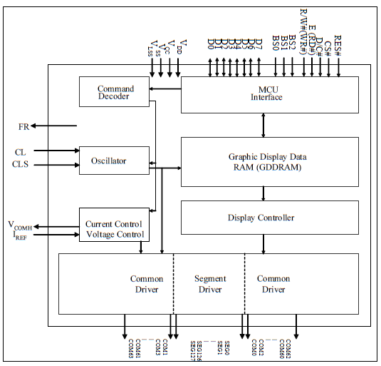
The output pins of SSD1306 are of multiple types. All of them are:
Driver Power Pins
There are a lot of pins in the driver which act as a power pin. some of these pins are for power/current reference and some are for power/ground input. All those pins are:
- VDD
- VCC
- VSS
- VLSS
- VCOMH
- VBAT
- BGGND
- IREF
Driver Signal Pins
All the signals pins contain all those pins which generate the signal for OLED. Like clock, enable signal, command/data pins, etc. In driver, all these pins deliver the output signal on the base of the input signal. Some of these pins are data input pins, which are responsible for data input to the driver. All the output pins are:
- CL
- CLS
- RES#
- CS#
- D/C#
- E(RD#)
- R/W#(WR#)
- D[7:0]
Pixels Pins
Some pins of the driver are divided in the form of columns and rows. These pins are responsible to select each pixel on the OLED. The OLED receives the signal from these pins and shows the value. These pins receive the value of digital pins and glow each pixel. All these pins are:
- SEG0~SEG127
- COM0~COM63
NC
The remaining pins are the no connection pins in the driver. Some of them are for test and some are just dummy. They have no use in the OLED display.
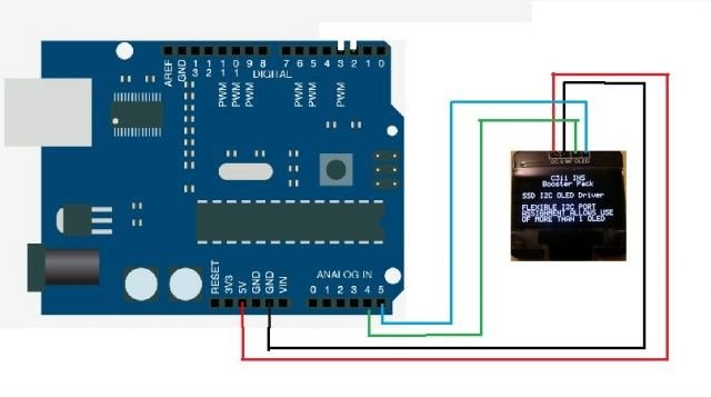
How to Interface OLED Display with Arduino Board?

Any microcontroller or board is must require for using this OLED display, for display purpose. So different people use different controller but here we shell the user how interface this display with Arduino board. First of all, one thing should be keep in mind some of the displays has swapped ground (GND) and VCC pin therefore the user should be make sure before connecting the OLED display with the Arduino board. The interfacing connection of Arduino board with OLED display is shown in figure 3
Figure 3 The Interfacing Connection of Arduino Board with OLED Display
According to figure 3, because it is operated at 3.3 or 5 volts dc therefore it is directly powered up with Arduino board and for this GND and VCC pin of display is connected to Arduino board VCC and GND pin. Similarly, SCL and SDA pin of this display is connected to Arduino board A5 and A4 pin. After this, the program is upload in Arduino board using Arduino library with the help of Arduino IDE software. Suppose we want to display “hello word” then program is upload after writing this word.
How to use SSD1306 Monochrome 0.96 OLED Display?
The use of OLED is very simple with the Arduino. The only requirement is the library and the circuit. The library is interfaceable with both SPI and I2C libraries. Even both the size and types of OLED operates able with the library. Here, the following circuit will use in I2C OLED.
To use the OLED the following libraries needs to initiate:
#include <Wire.h> To use the I2C communication this library is required
#include <Adafruit_GFX.h> //To use the any Adafruit Graphical interface the library is required
#include <Adafruit_SSD1306.h> //This describes the driver type.
The only reset pin needs to describe. If there is no requirement of usage of reset pin, then enter the -1.
Adafruit_SSD1306 display(-1); // Change the value to pin number in case of its useage.
Then initiate the OLED in the setup:
display.begin(SSD1306_SWITCHCAPVCC, 0x3C);
To show the text on the OLED the following commands will help. In the text display command the fonts, size, and types are changeable. The cursor will decide the position of the font. To show the new text first clear the previous data from the buffer. Then also display command is required to show the new text.
display.clearDisplay(); //To clear the display
display.setTextSize(1); //Set the text size
display.setCursor(0,28); //Set the text position
display.println("ENTER THE TEXT"); //To show the text here
display.display(); //To display the text
Multiple other functions can be performed with the OLED. The OLED display is also invertible according to the requirement. The images needs to convert to bitmap to display on the OLED.
2D Diagram
